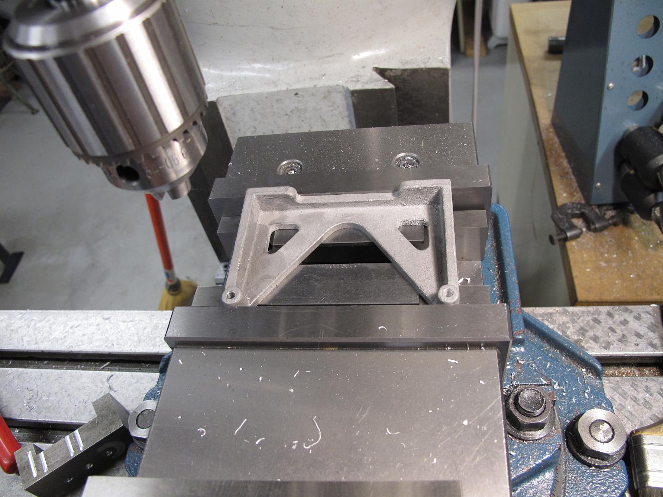
23-July-2010 Bill starts work on the Reverse Stand
The machined lower reverse stand.
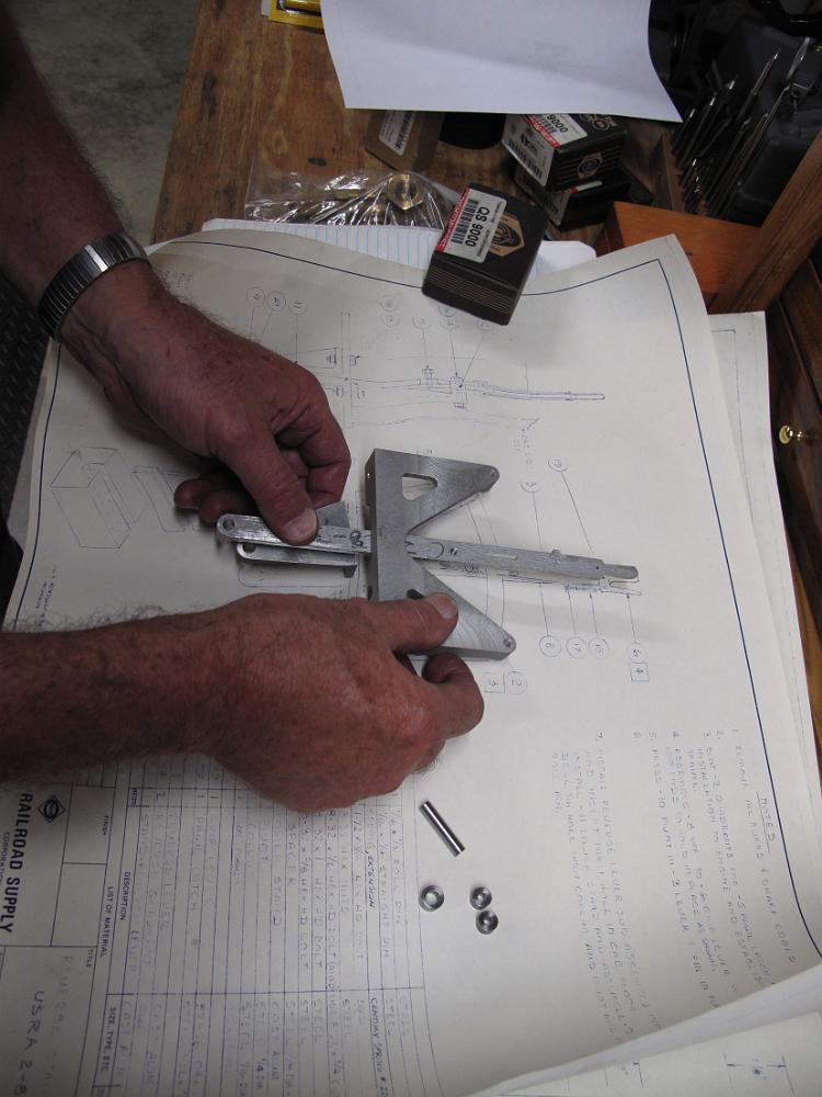
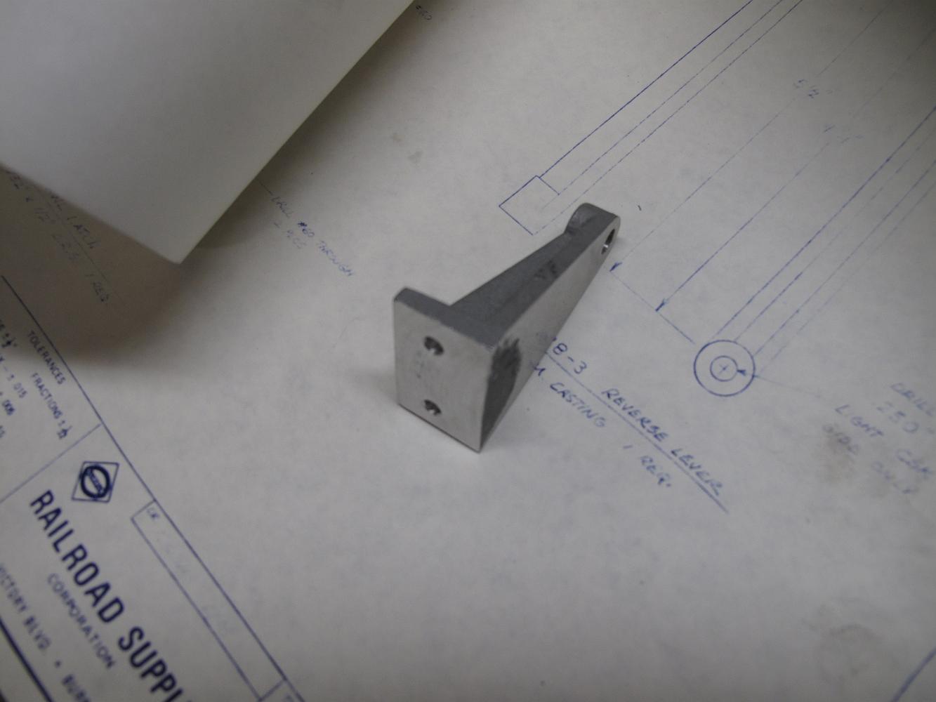
4-Aug-2010 Trying to figure out the proper assembly of the reverse lever. There are three drawings in conflict with each other - The cab assembly view, reverse…

4-Aug-2010 After some 'get dimensions by scaling from the print directly', the quadrent bars are drilled.
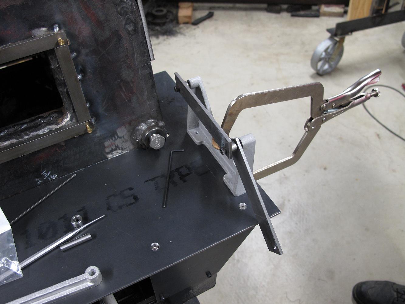
13-July-2011 Positioning the reverser on the cab floor to cut out the lever opening.
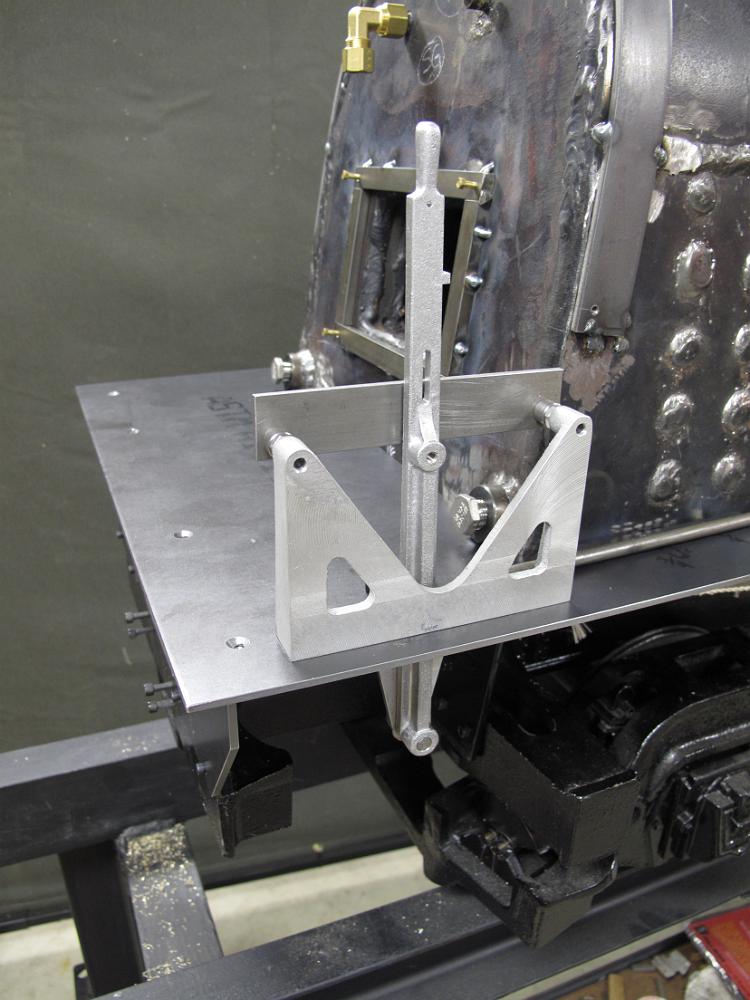
Test fitting the reverser after we cut an opening in the floor.
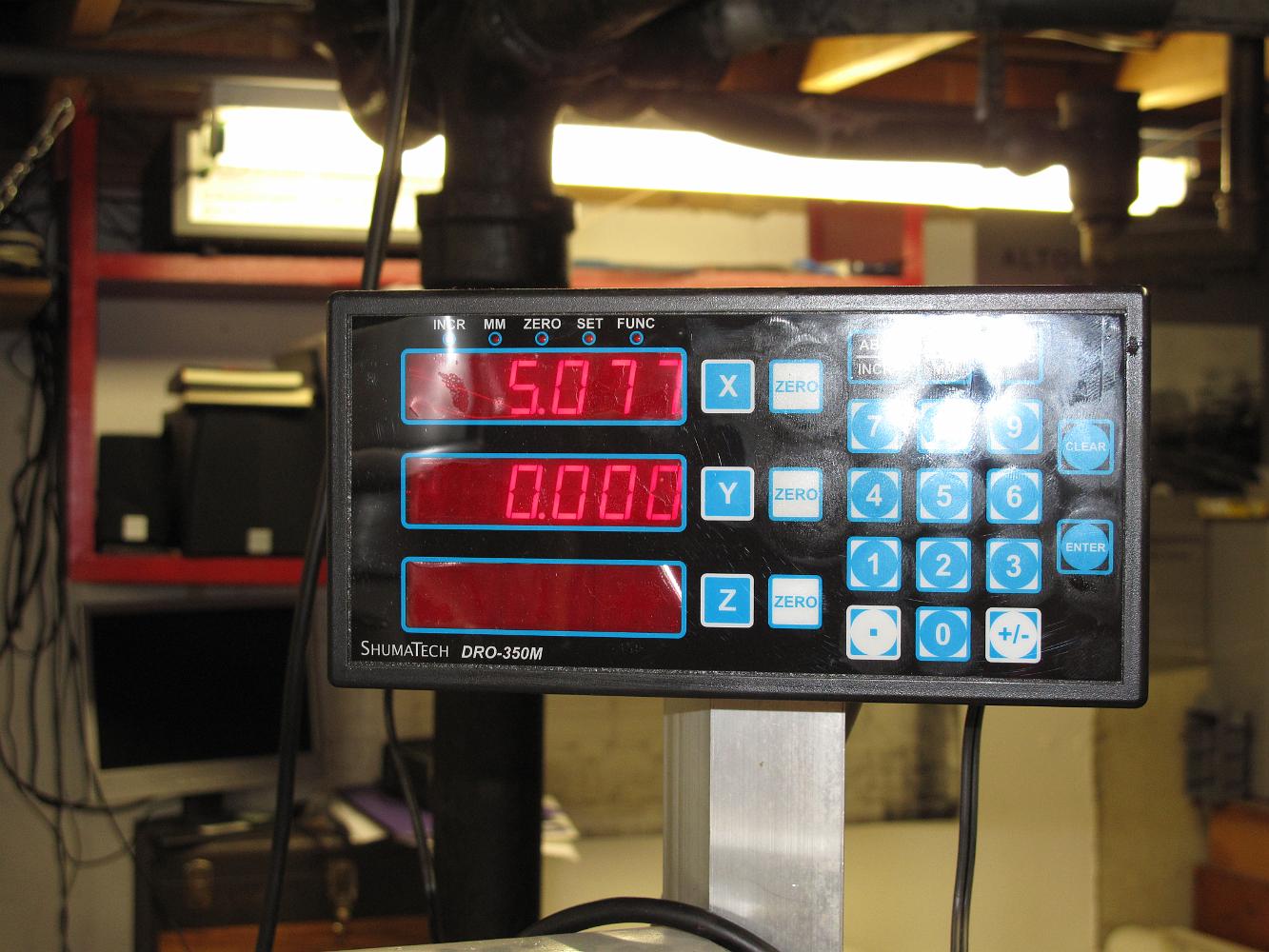
20-July-2011 After much figuring and consulting the geometry/trig/triangle sections of the Machinists Handbook, we calculate the distance from the centerpoint…
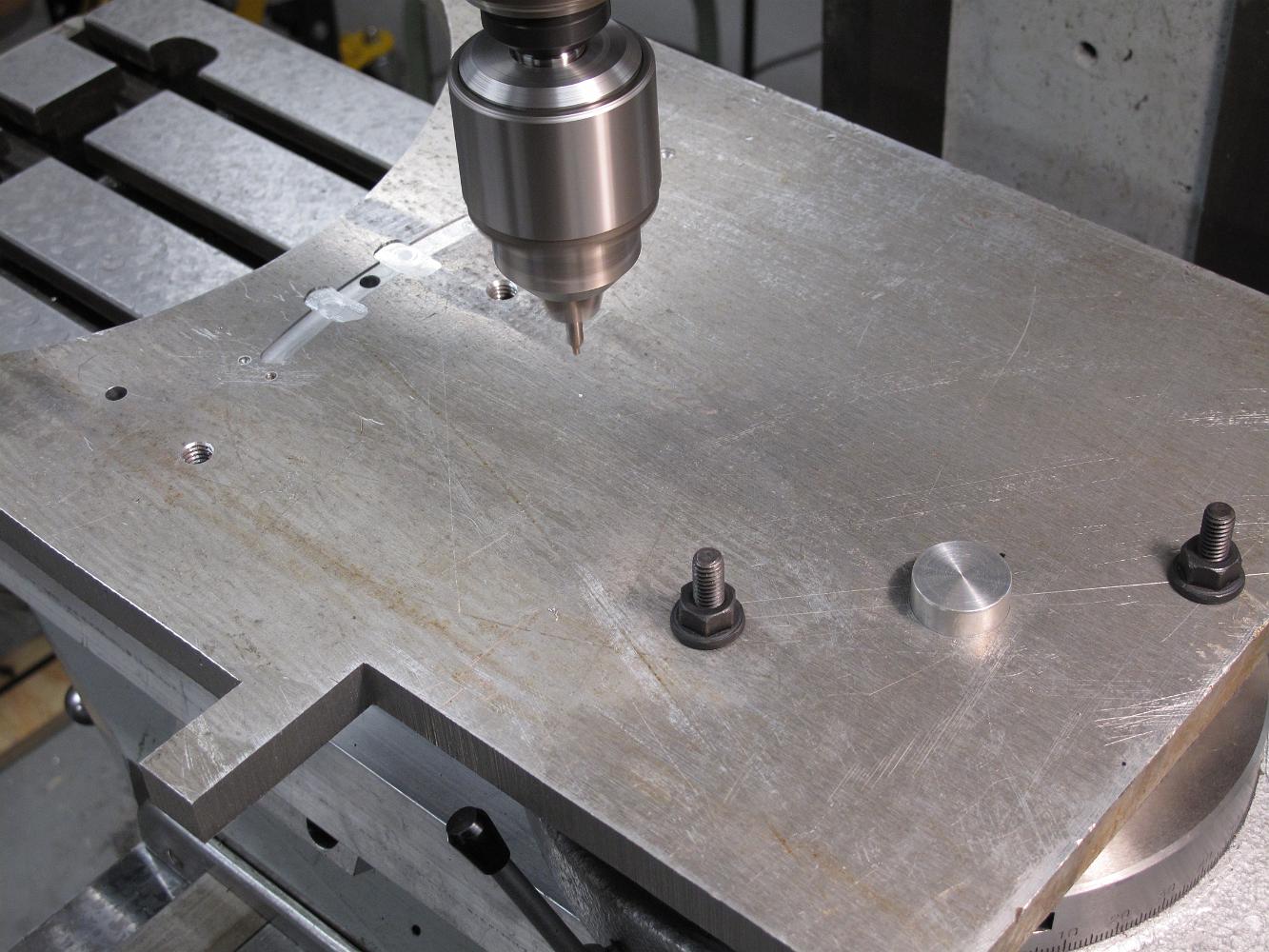
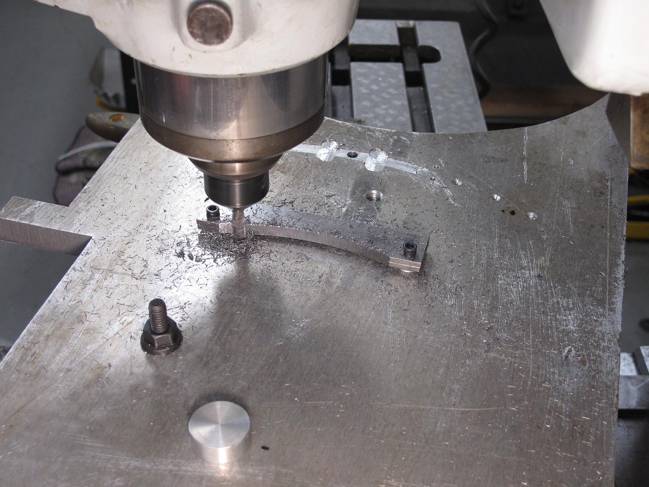
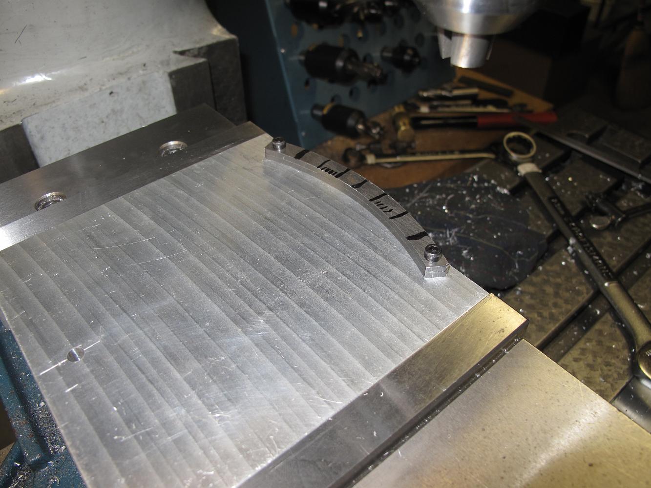
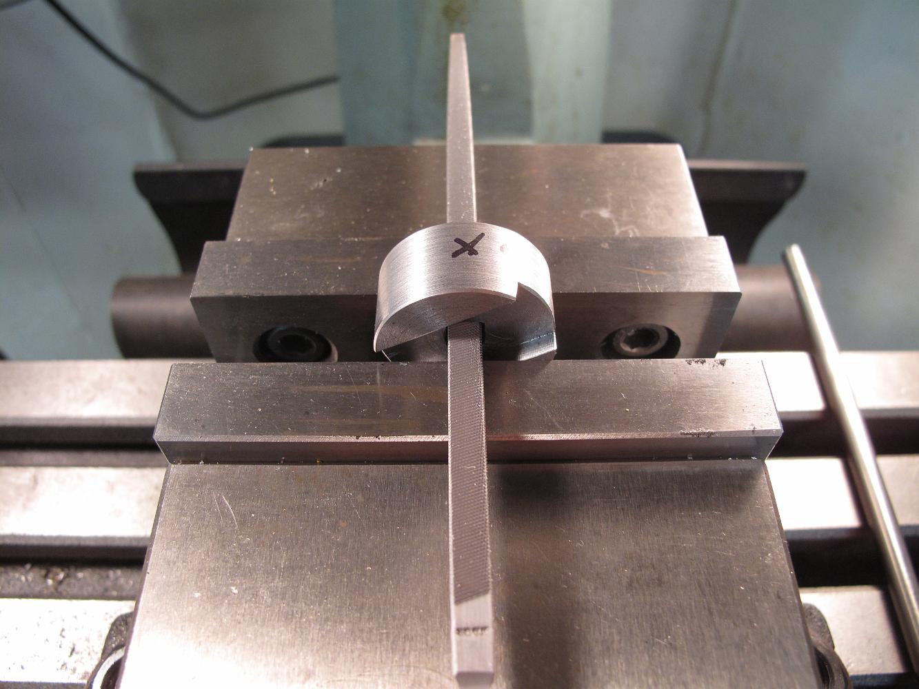
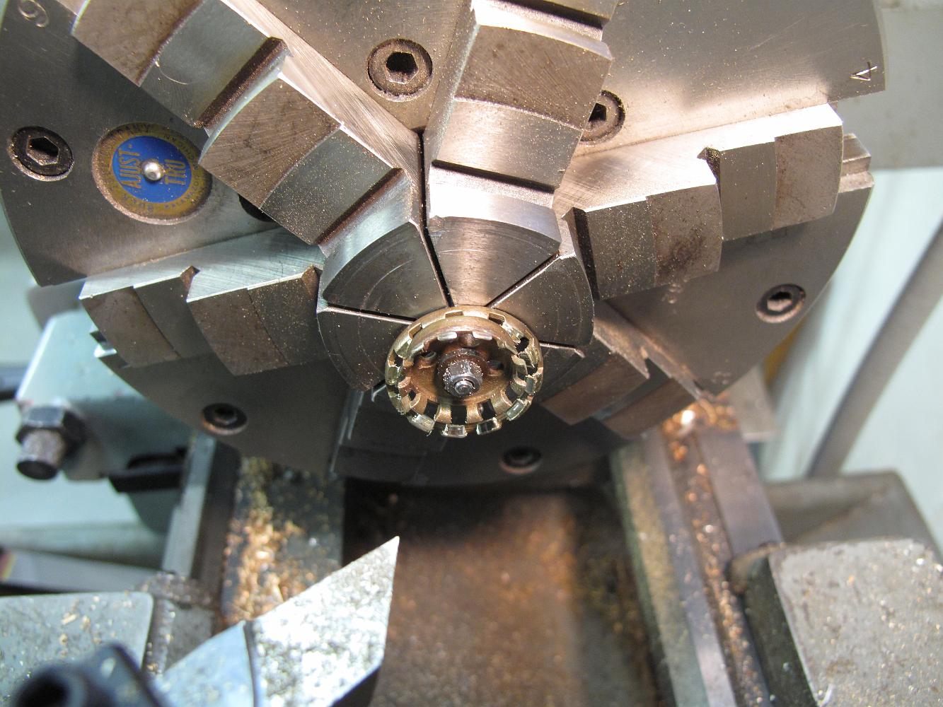
20-July-2011 With the rotary table back on the mill and the sacrificial worksurface bolted to the top, we are ready to radius the reverser notch bars. The plug…
20-July-2011 The bolt holes have been drilled in the table and the bars to be radiused are bolted down for machining. We put a couple sacrificial washers…
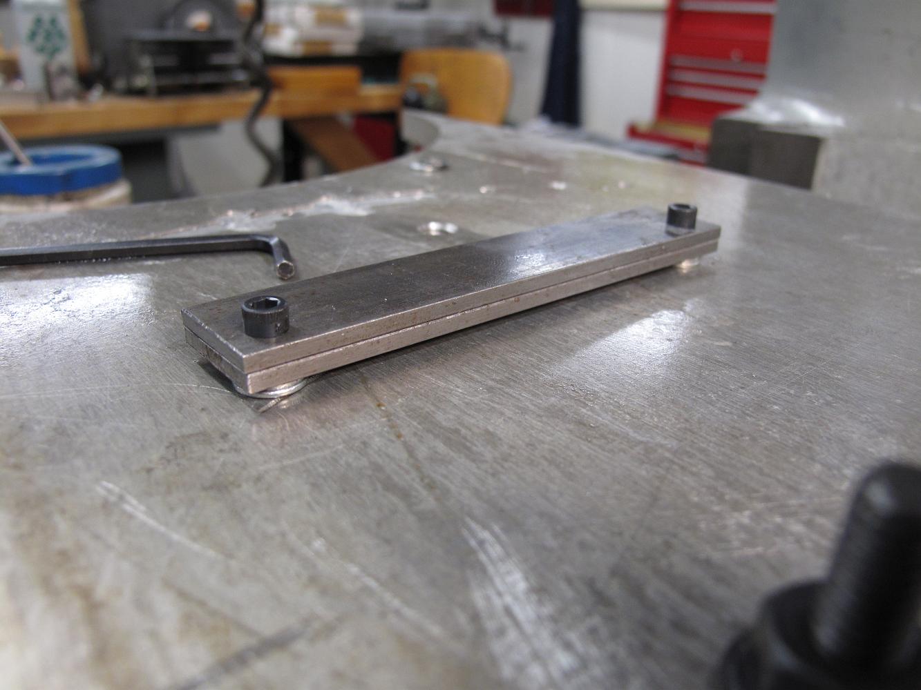
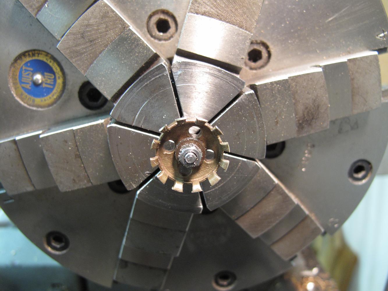
Conventional milling only, we take small cuts - 0.010 to 0.015 each pass.
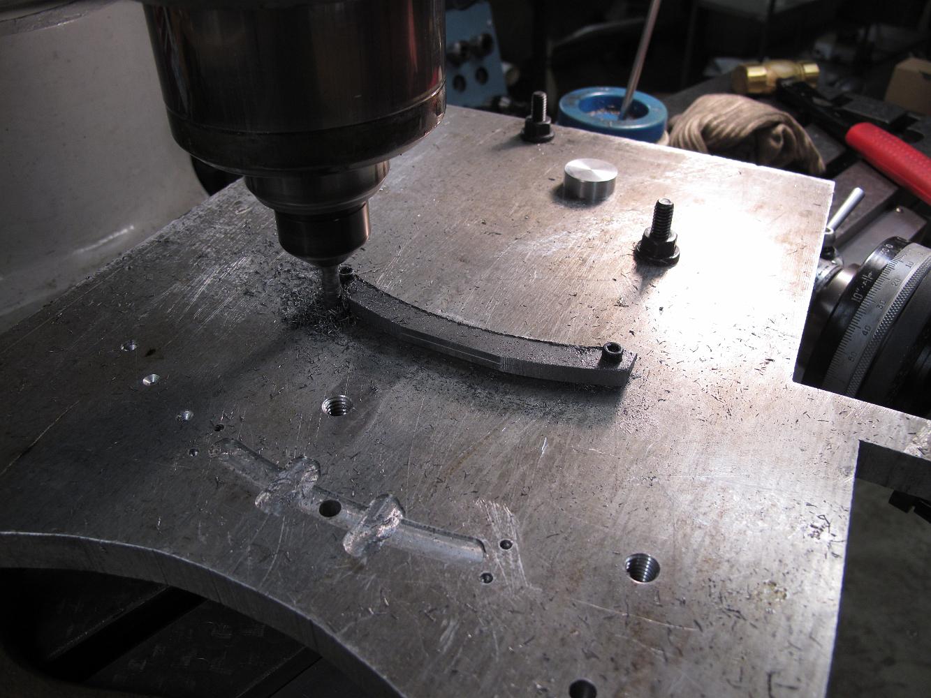
An hour later, we are almost done making a square bar curved!
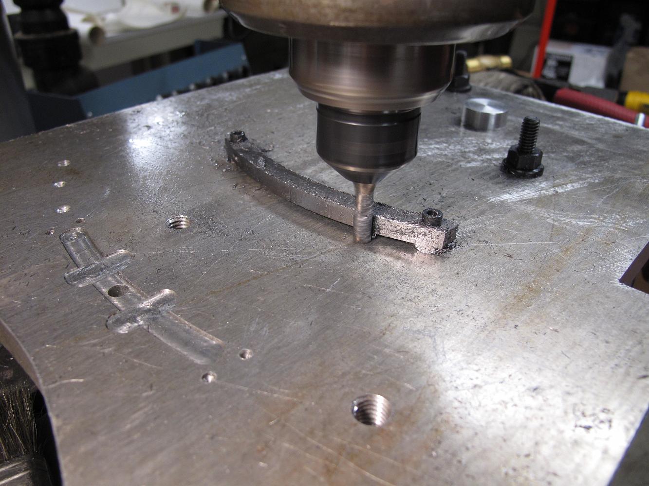
20-July-2011 on the very last pass, taking only a 0.002 cut, we climb mill for a nice finish.
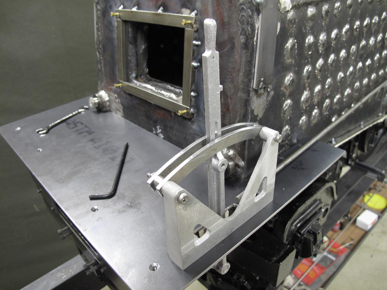
20-July-2011 The reverser with finished notching bars installed.
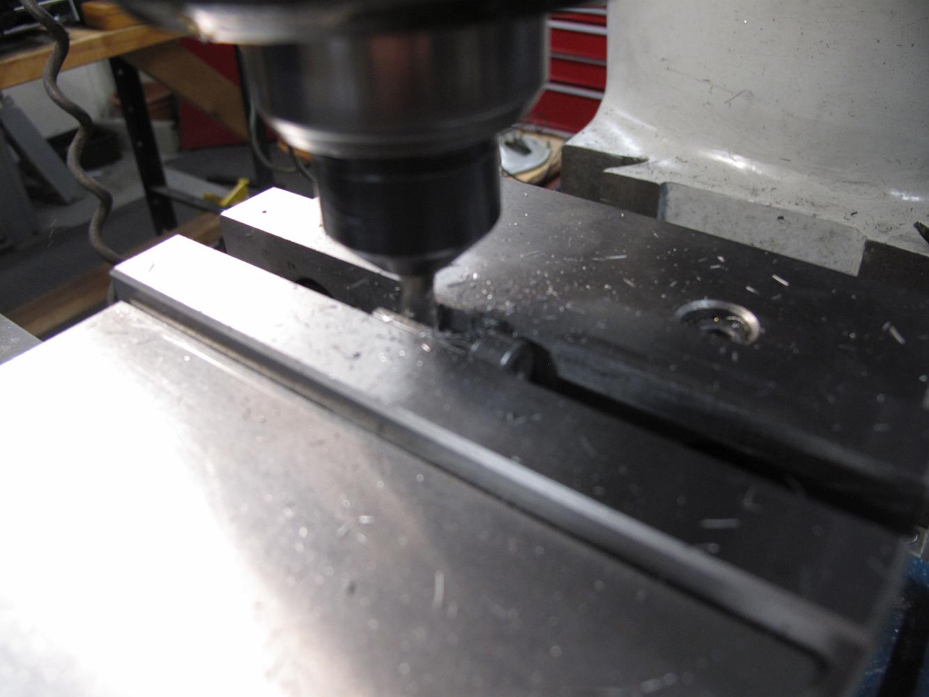
27-July-2011 Milling a 'half' clevis for the reversing lever.
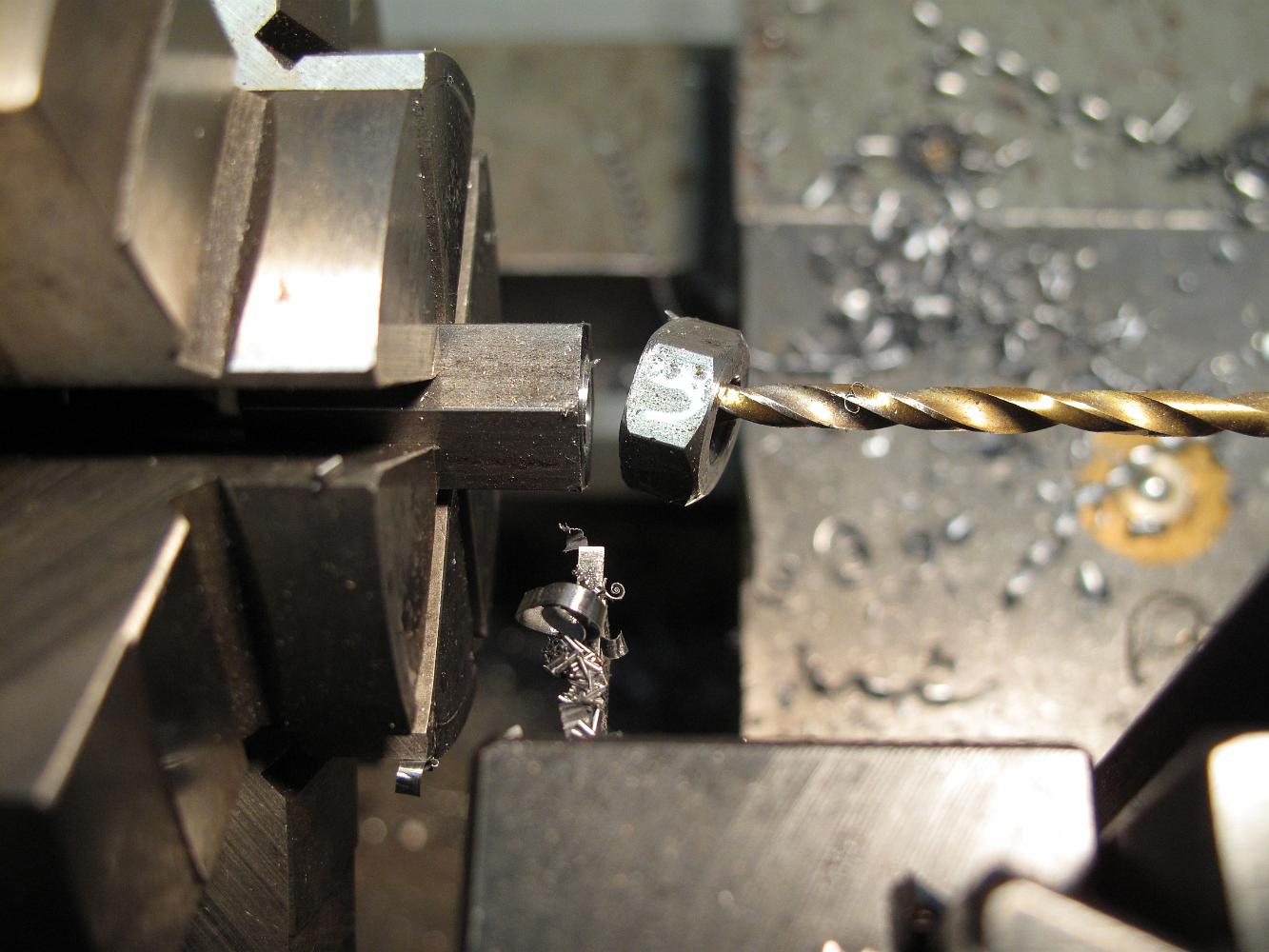
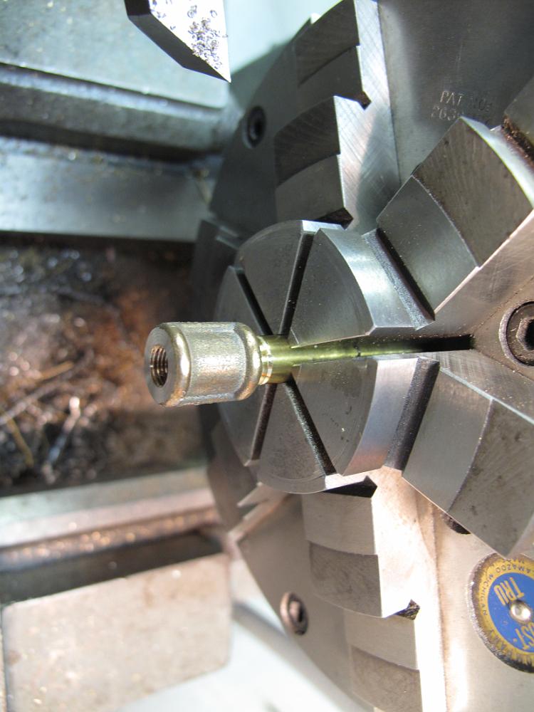
While Bill was working on the clevis', I turned a 1/4-28 left-hand nut from some 7/16 hex stock. The drill is just to catch the nut from the parting off…
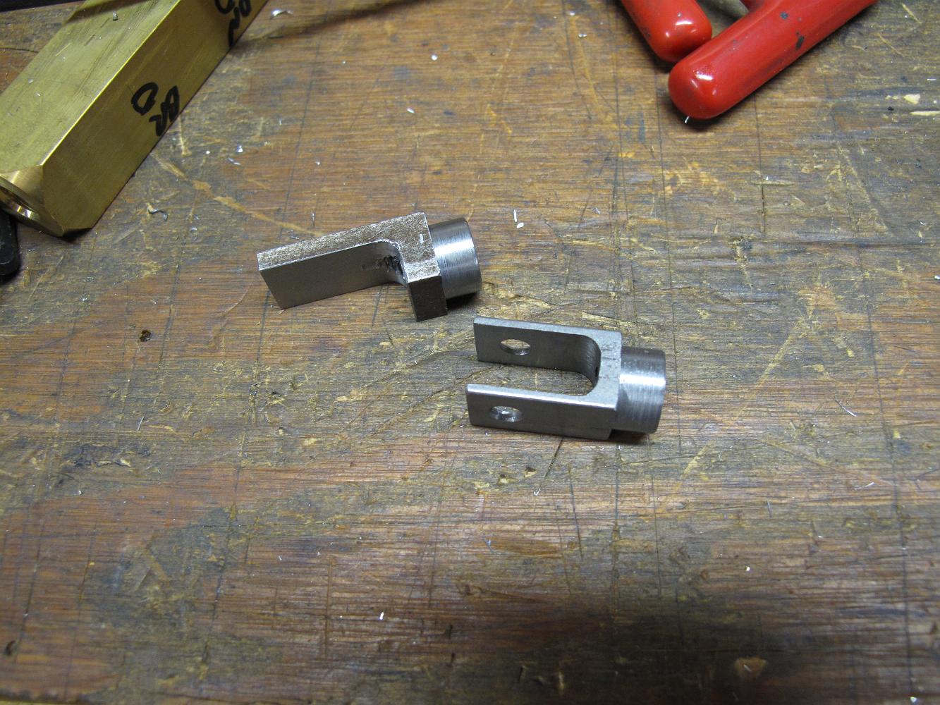
27-July-2011 The top 'half' clevis is for the reversing lever, the bottom for the tumbling shaft lever. The top one is stamped with the letters "LH" since it…

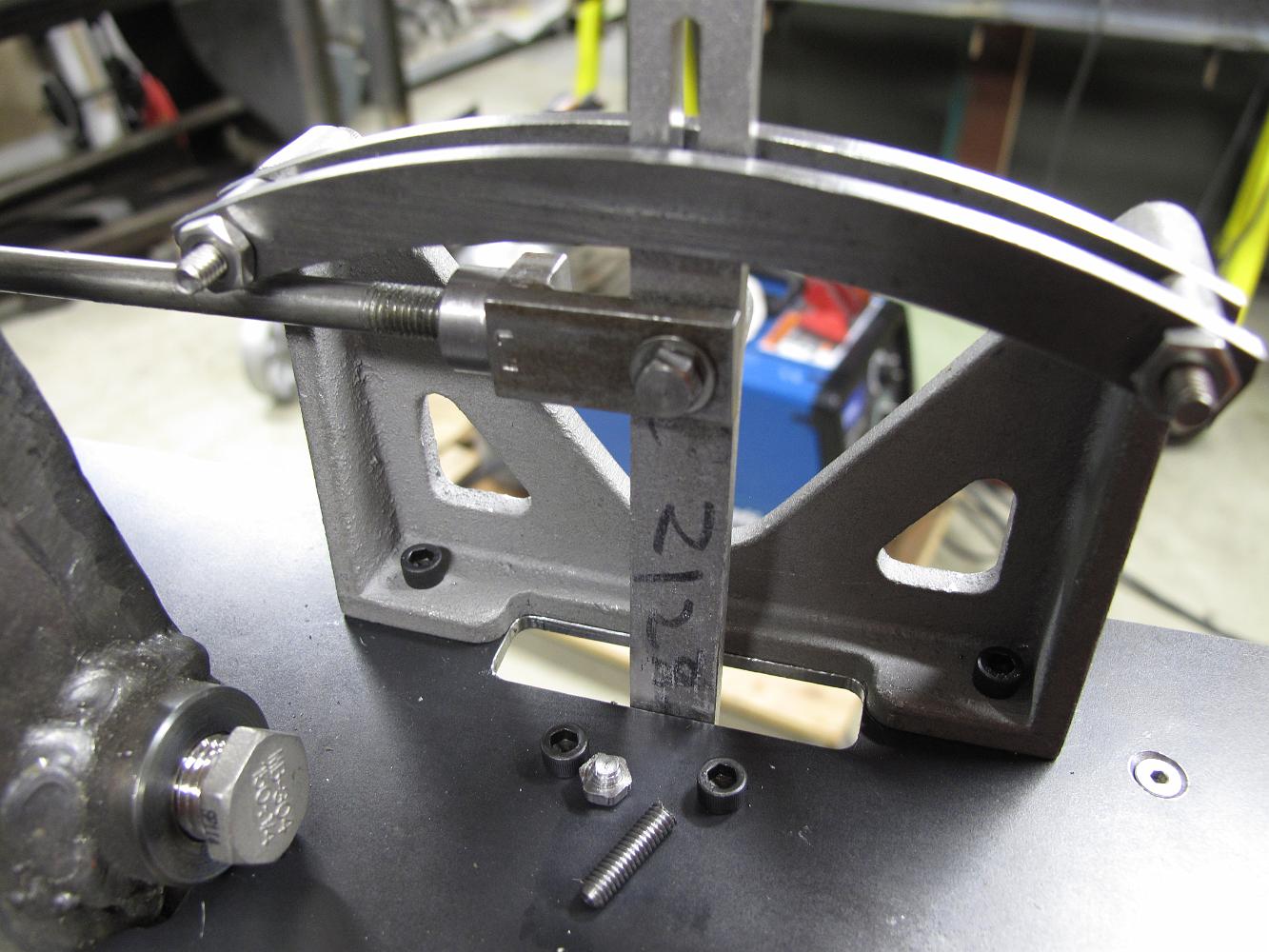
27-July-2011 The reverse stand with reach rod installed. We used a 1/4" rod, bigger than the prints call for, thinking we might need the higher rigidity a…
27-July-2011 Closer up view of the 'half' clevis installed on the reversing lever. We turned a #8-32 steel model bolt down so the half clevis was bearing on the…
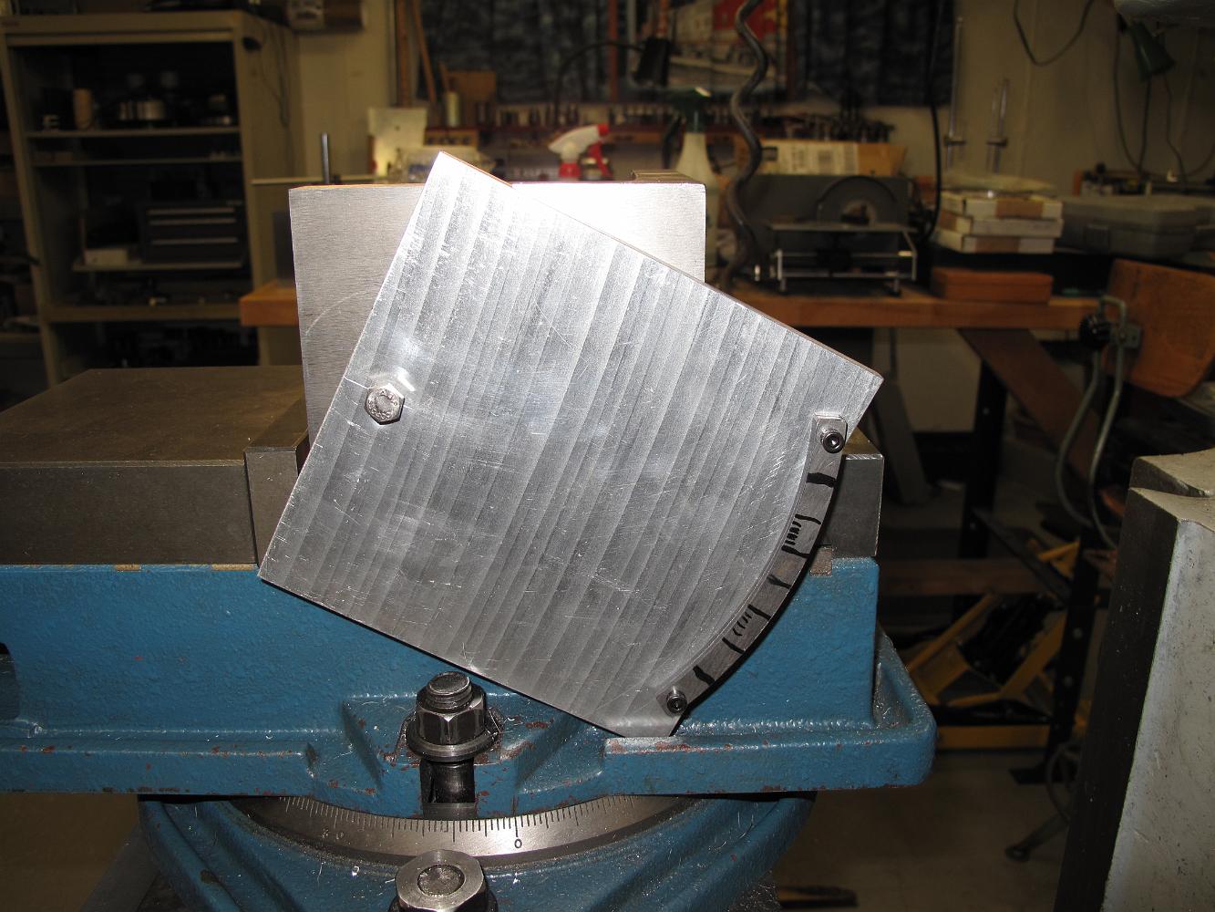
17-Aug-2011 Making a poor mans dividing plate to cut the quadrant slots.
The pivot point drilled on the left, two holes are drilled and tapped 5.077" from the centerpoint to make the quadrent notches on a 5-9/32" radius.
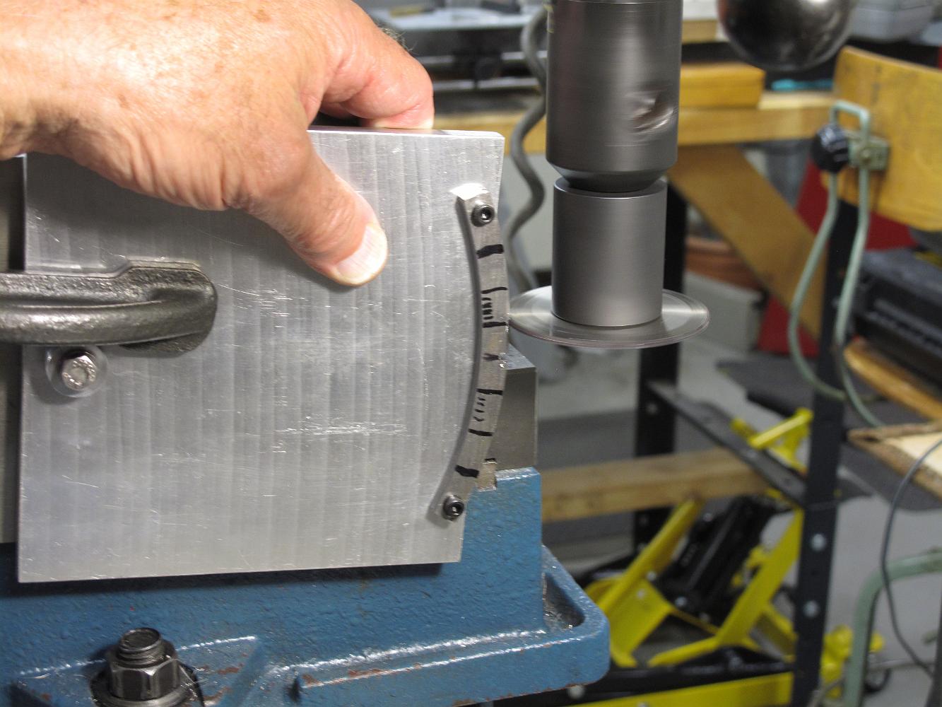
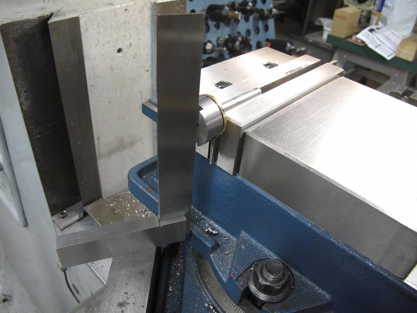
Bill didn't like clamping the edge of the angle plate in the vise--it puts a lot of twist on the movable jaw and is a small contact point--so a scrap metal bar…
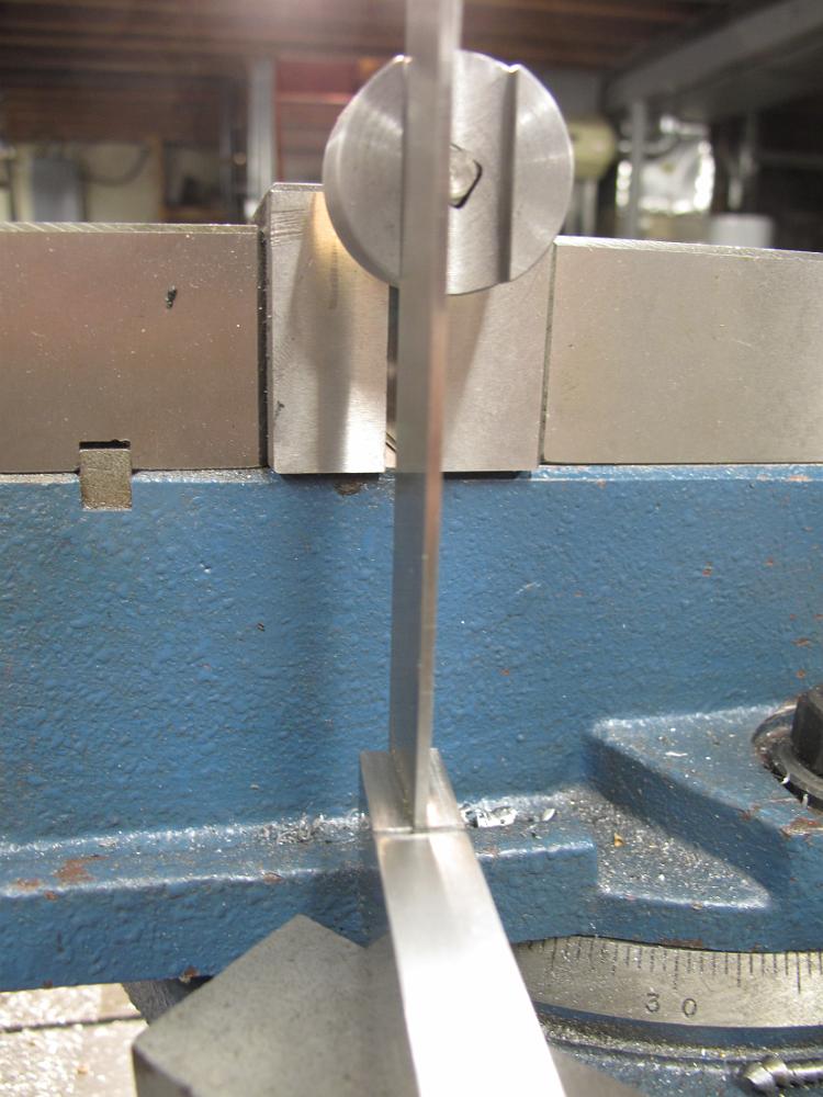
No, he's not holding the plate in place while we machine the slots, the c-clamp is doing that. But he is feeling how the cutter is doing and feeling for…
17-Aug-2011 The revering stand with notch graduations cut. The first notches away from center are 1/2" apart. The notches are 0.040 wide and 3/32" deep. They…
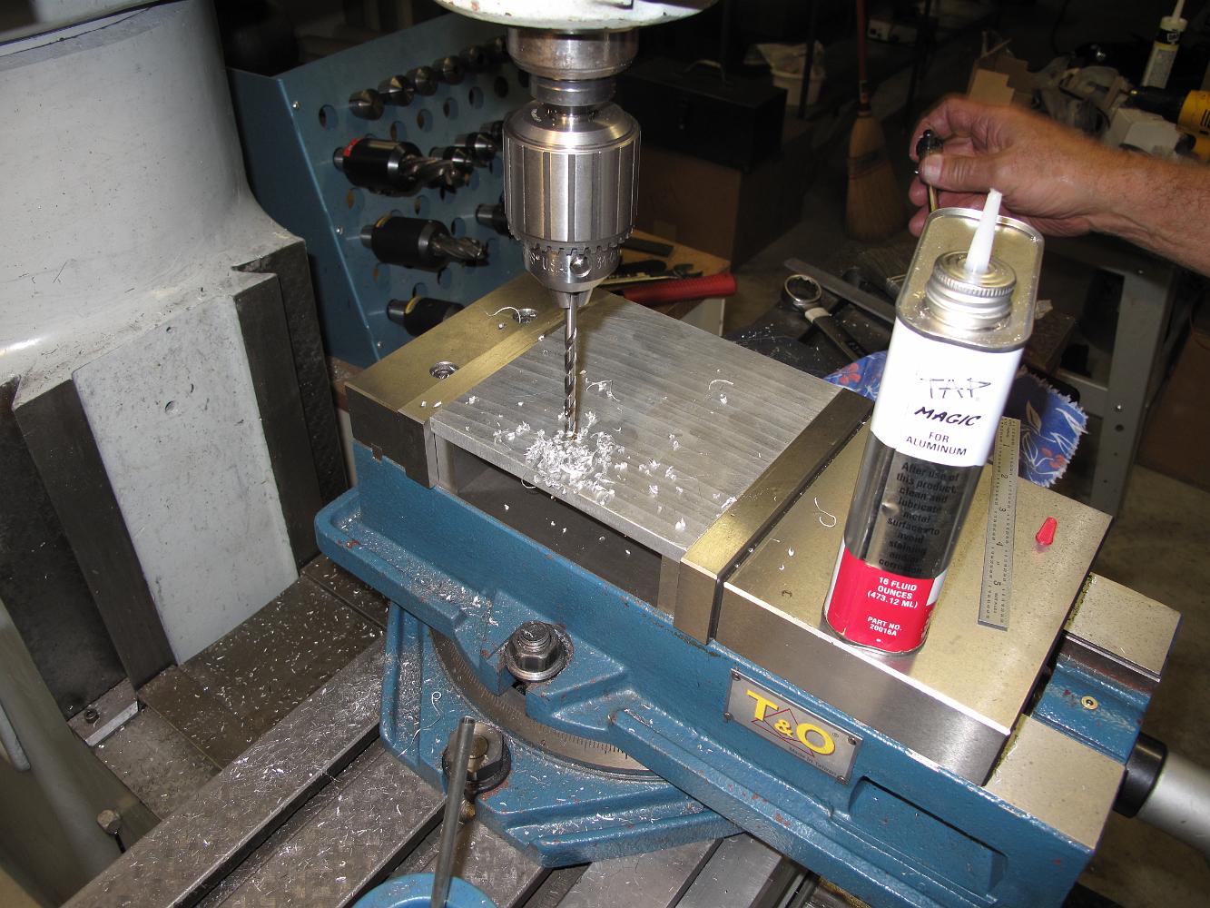
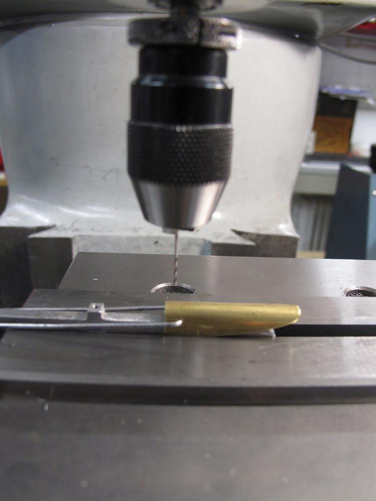
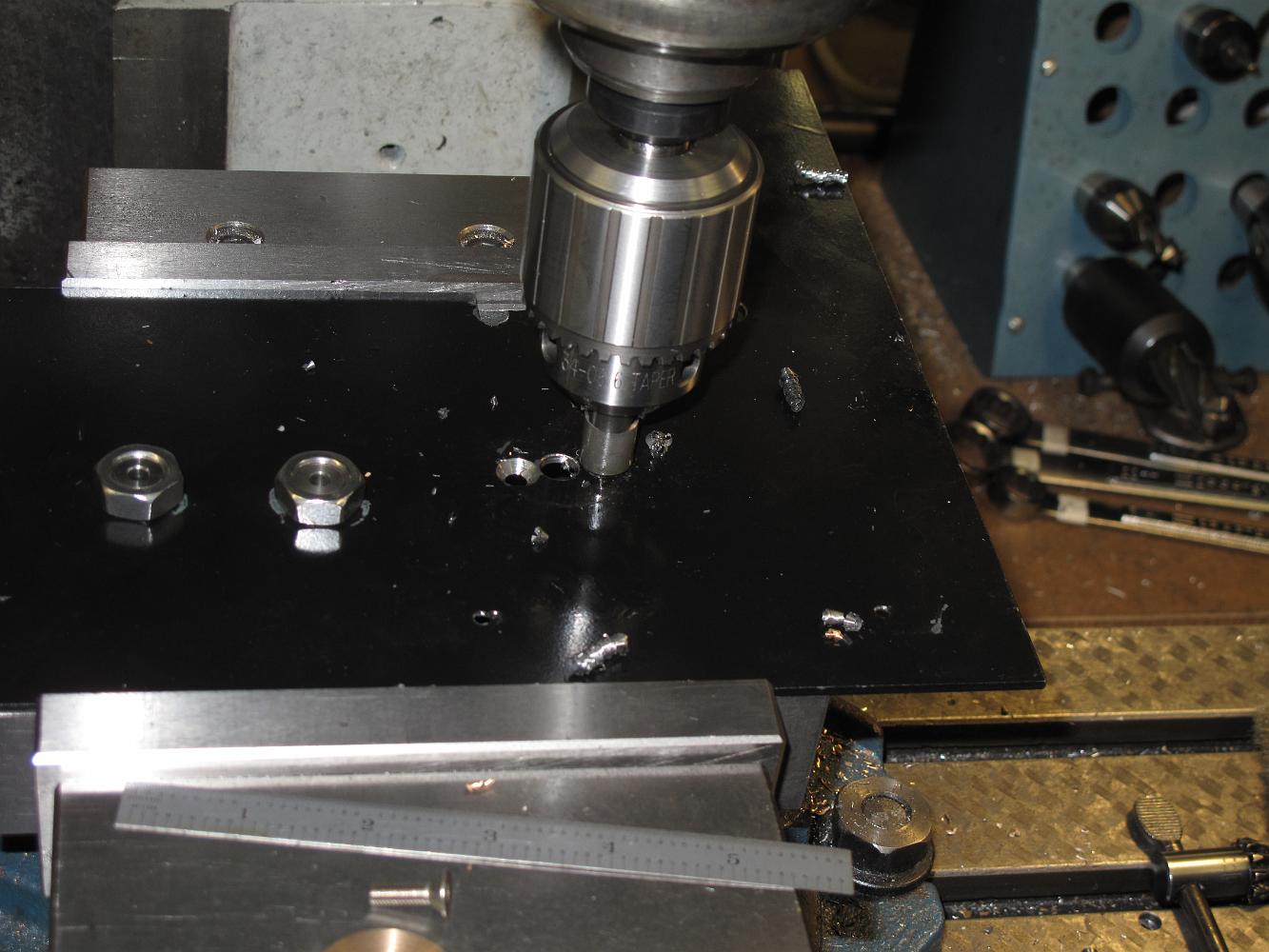
24-Aug-2011 Using a #78 drill bit to drill the spring hole in the handle with a sensitive drill attachment.
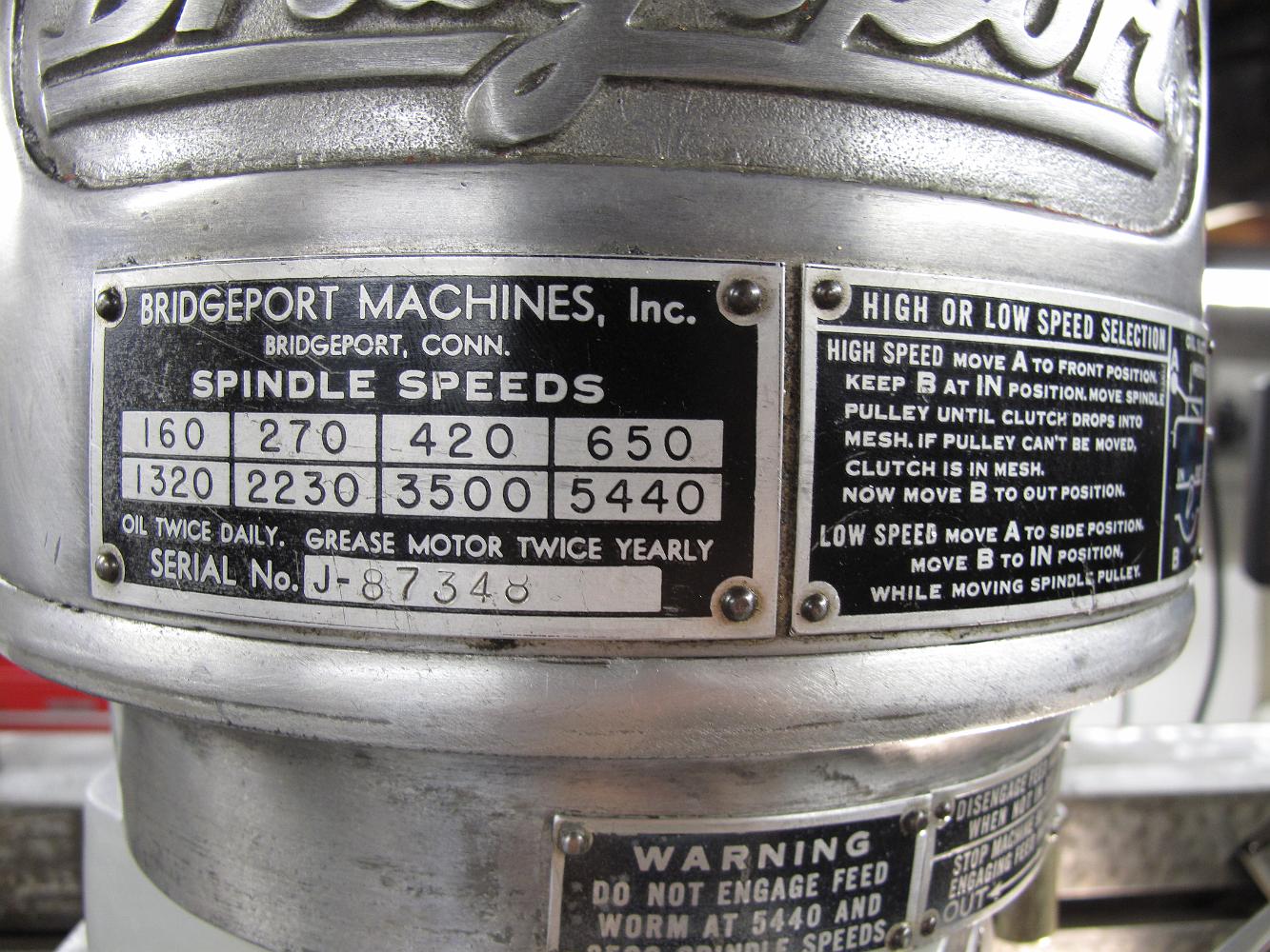
24-Aug-2011 Using such a small drill (#78) called for the fastest speed on my Bridgeport, which in this case is 5,440 rpm, quite a lot faster than a standard…
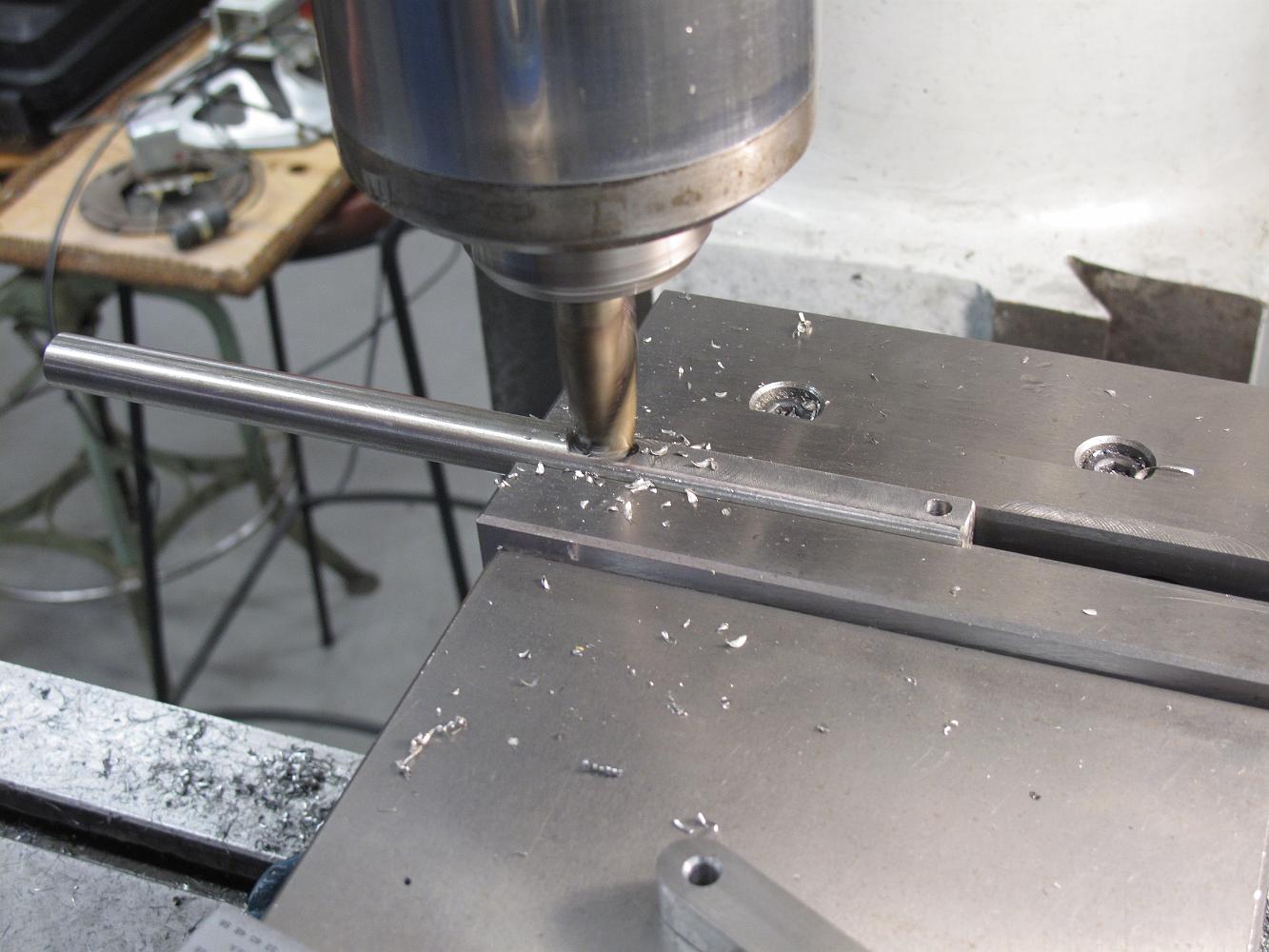
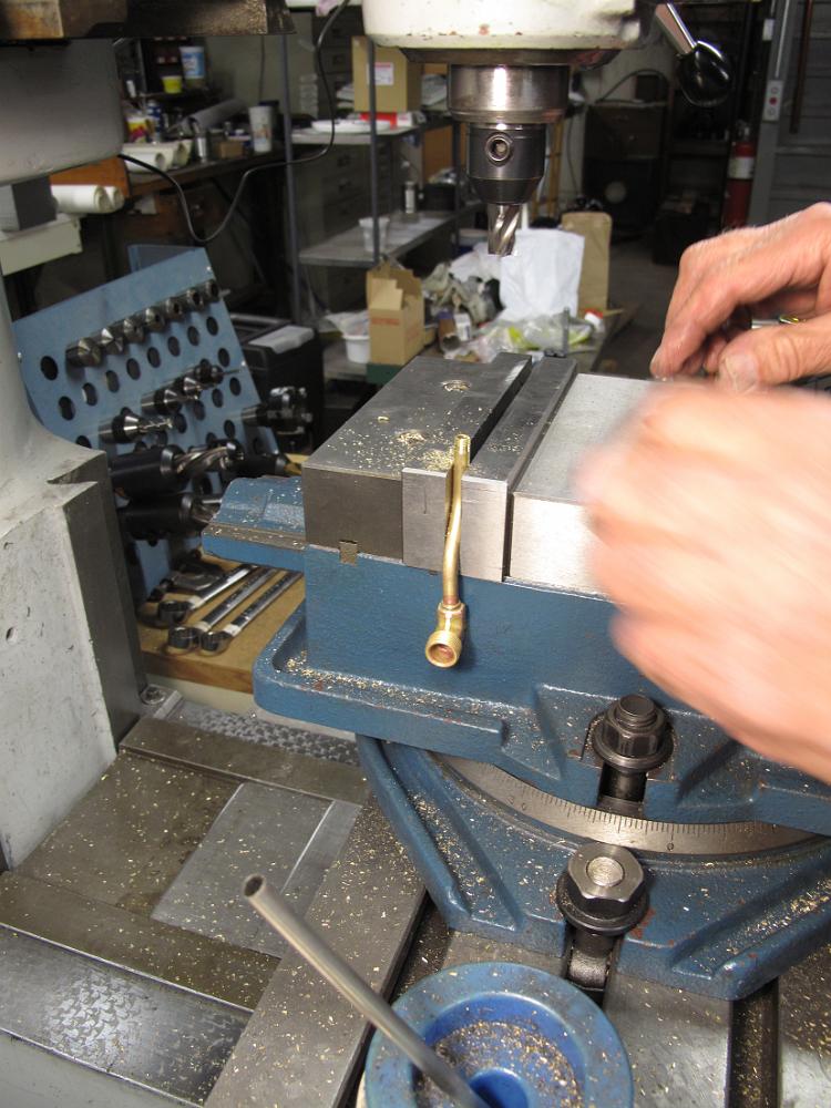
Milling a flat in the throttle handle. We decided not to use the 1/8" flat bar stock design, opting for a round lever. 1/2" 303 stainless steel, big enough to…
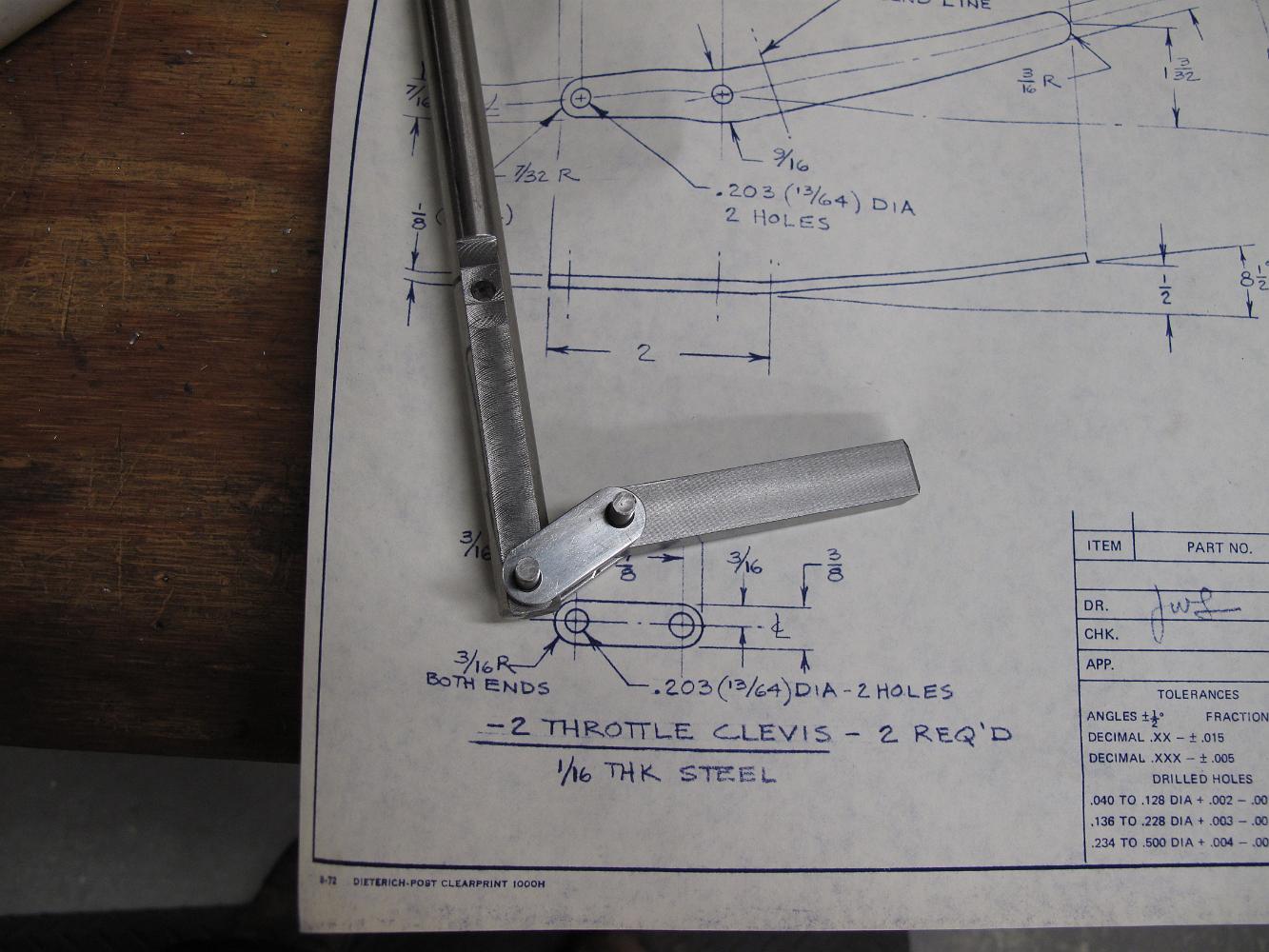
27-Aug-2011 I finished up the clevis links over the weekend. The boiler bracket is 2-3/4" long instead of the stub shown on the print to bring the throttle back…
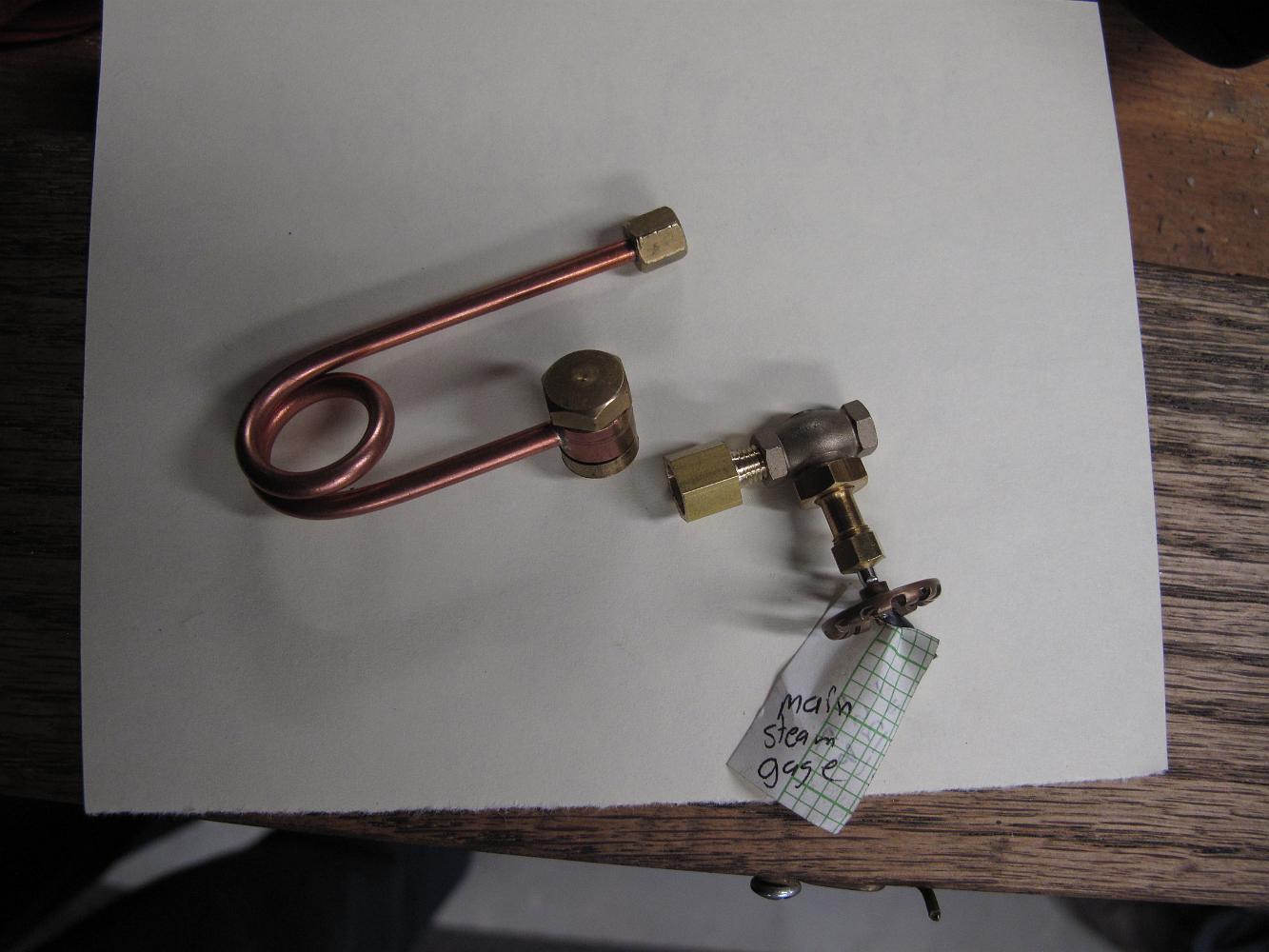
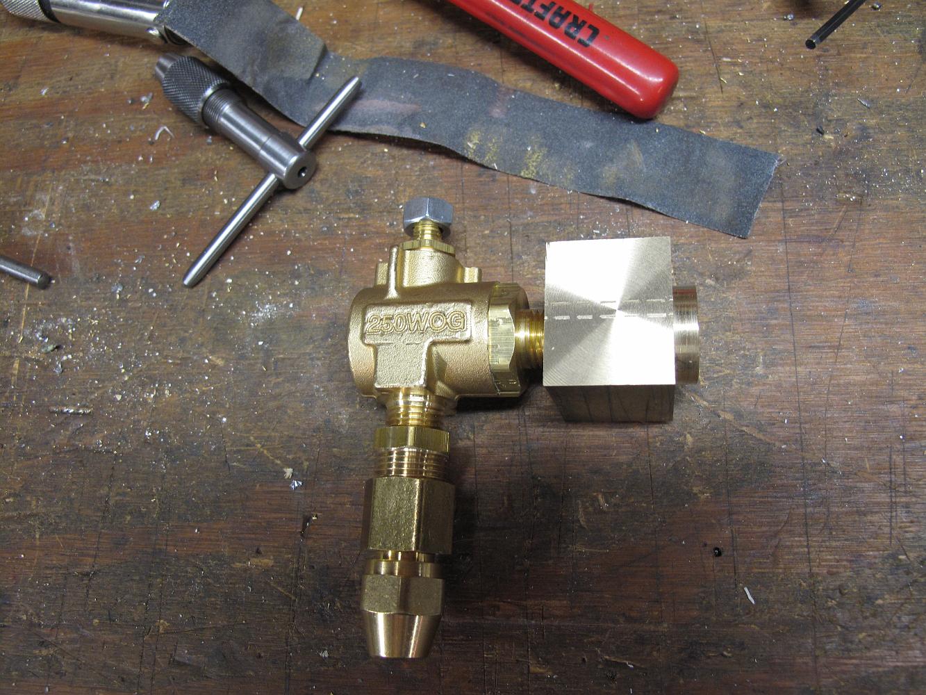
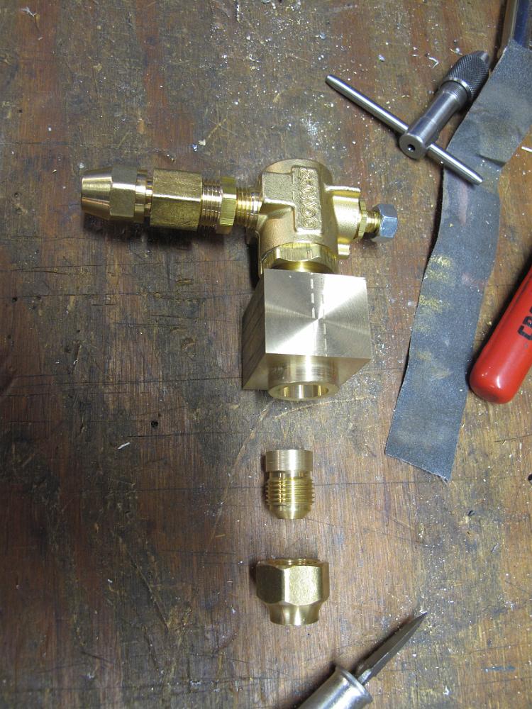
17-Oct-2011 Piping layout for main steam gage. The valve is from Superscale, street el from PM Research and gage from American Model Supply.
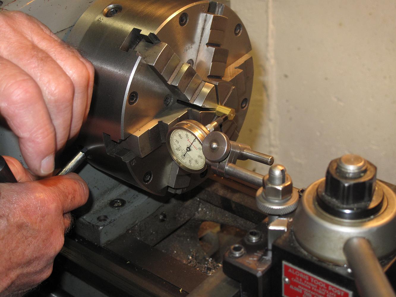
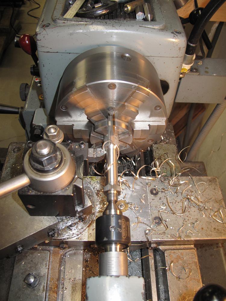
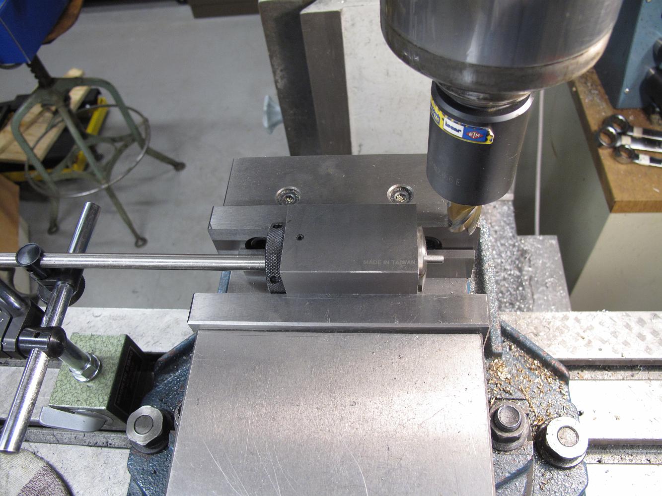
17-Oct-2011 Centering up a pierce of hex stock in an adjustable 6-jaw vise with an indicator. The indicator is mounted on a quick change tool holder. To use,…
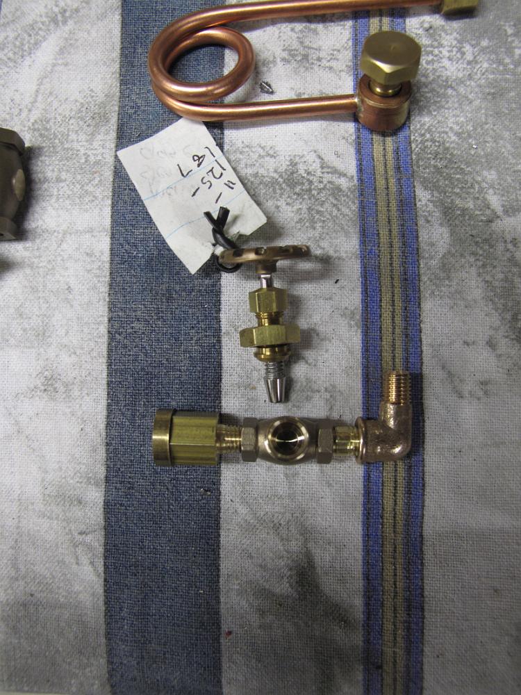
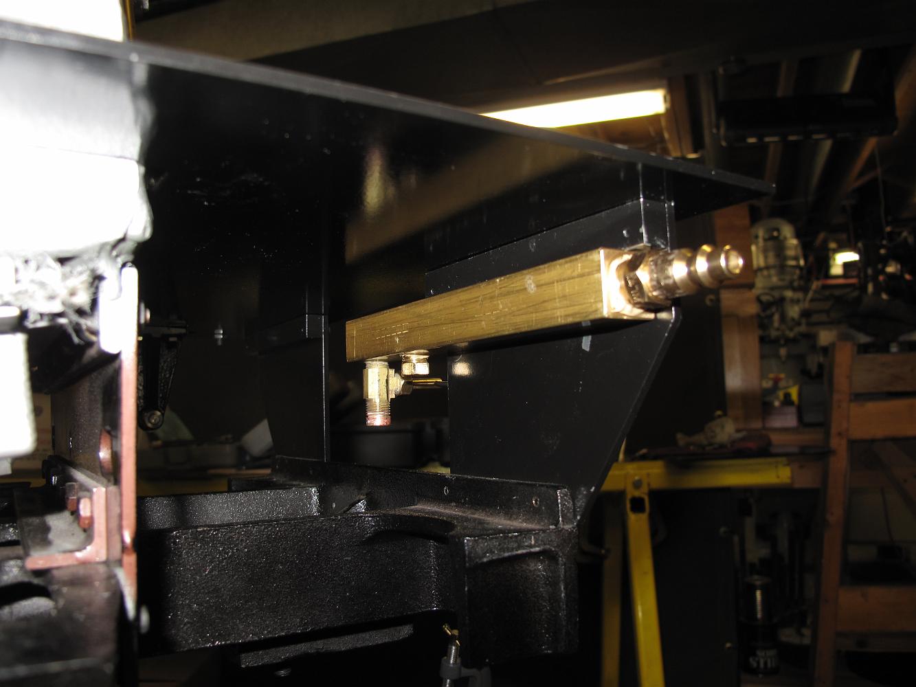
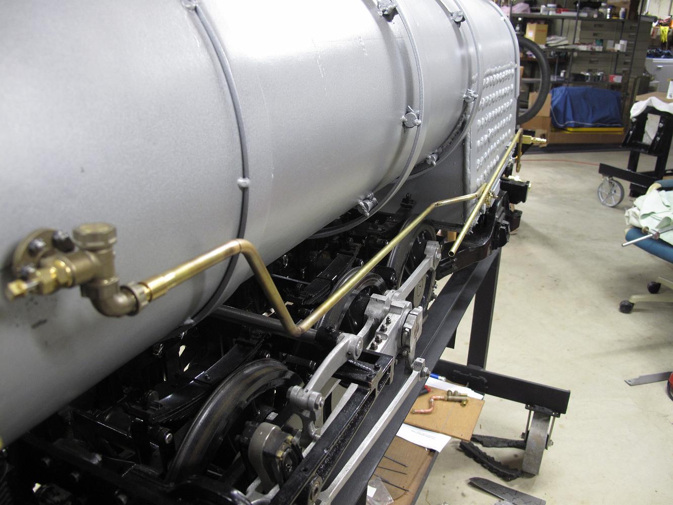
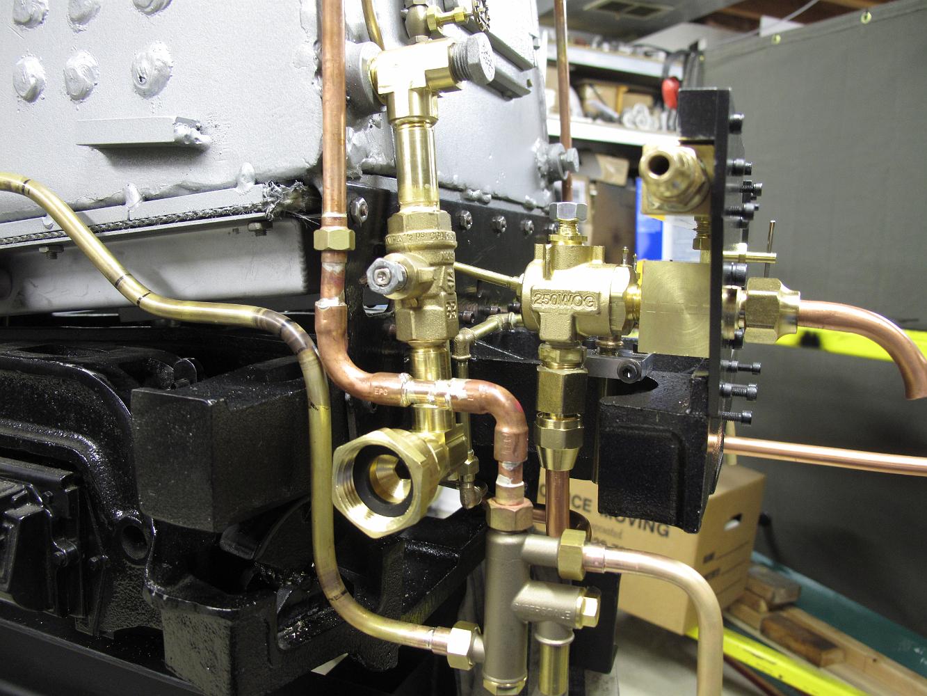
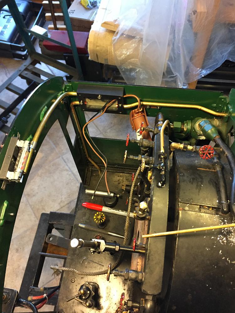
24-Oct-2011 Back to assembly! The now shorter manifold is (re)-installed on the boiler. On the right the main steam gage fittings have been installed, on the…
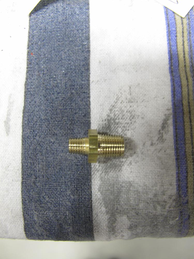
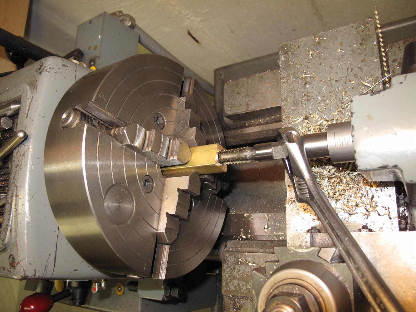
24-Oct-2011 Using the union as a holder, we make some close nipples. Here we are facing the brass pipe to length before threading.
24-Oct-2011 With adapter unions and adapter bushings installed, we begin to ponder how to position, place and pipe the waterglass.
24-Oct-2011 The left side of the cab next to the end of the turret is going to be a crowded place in regards to plumbing. We will try to sneak the water glass…
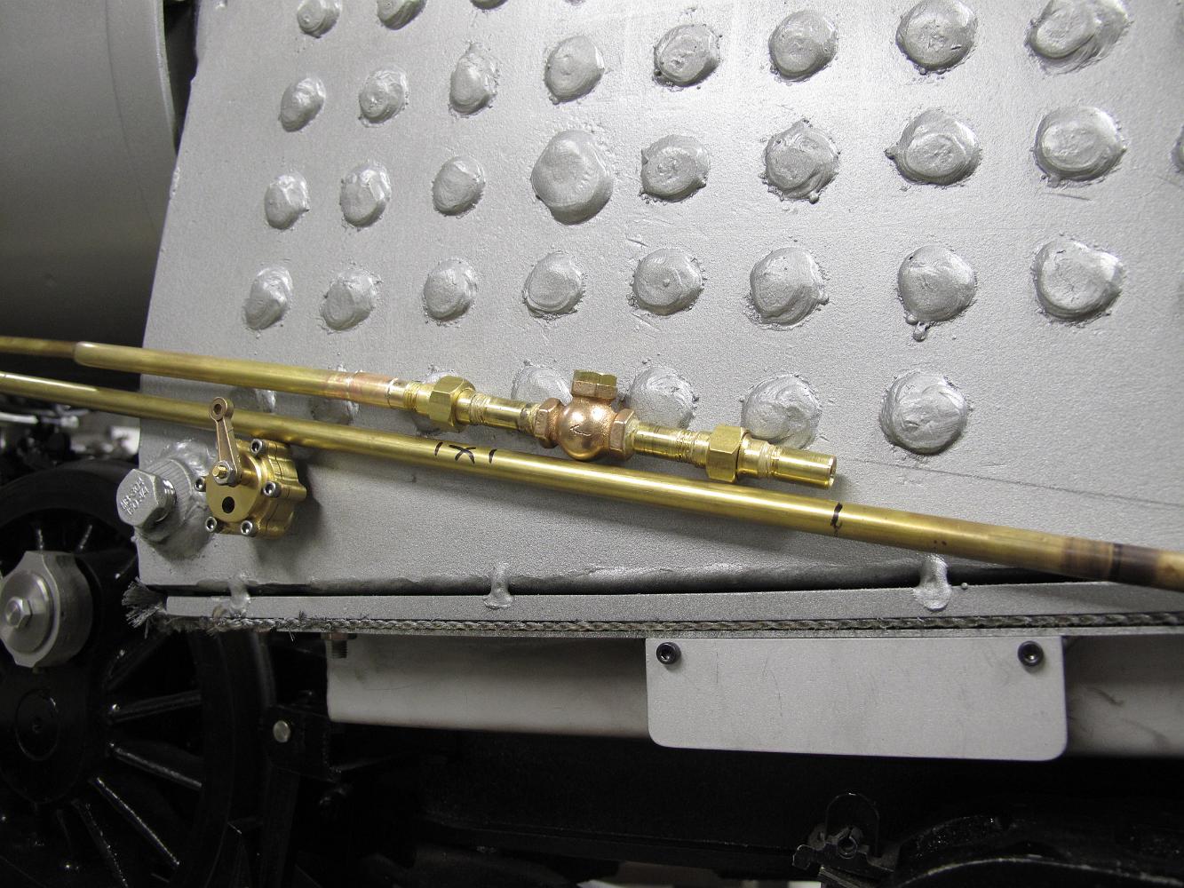
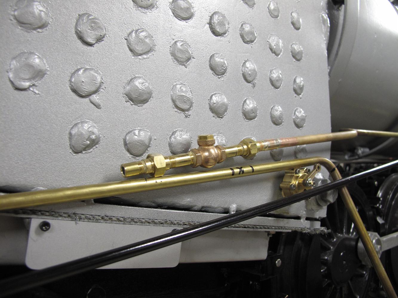
1-Nov-2011 Taking a little off the top. Although we measured the distance from the boiler fitting to the manifold valve, the exact distance to match the union…
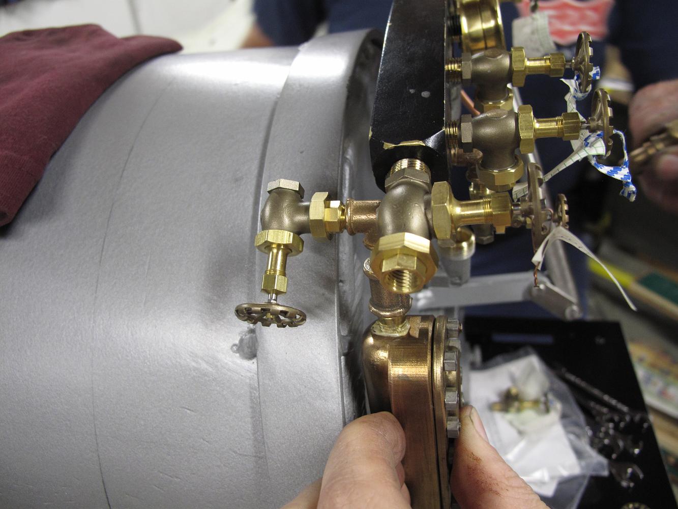
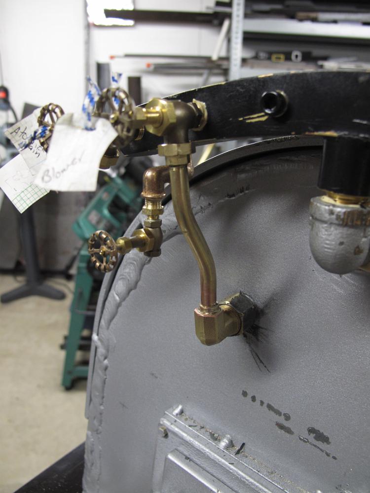
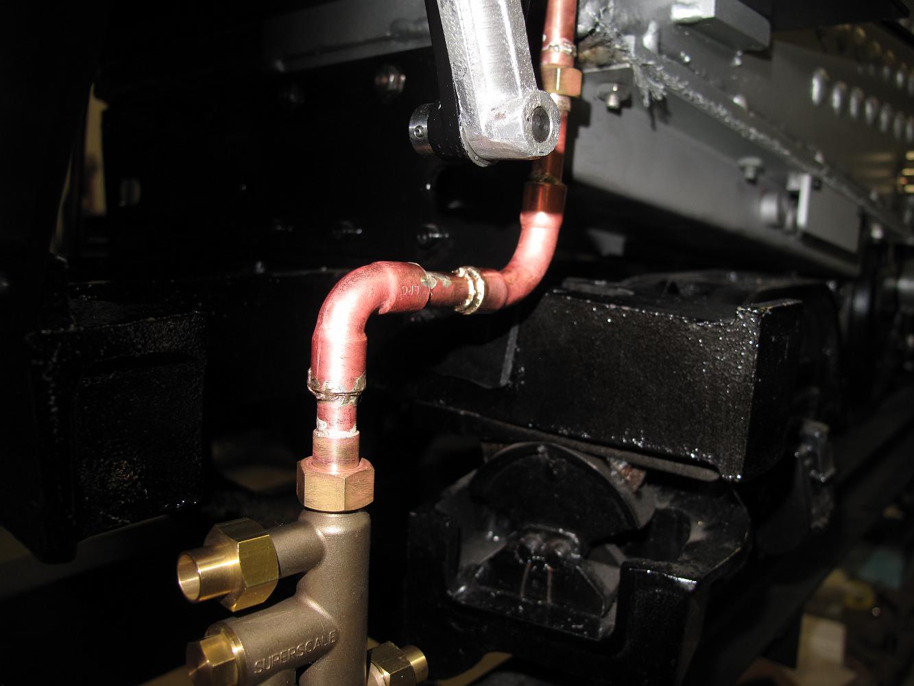
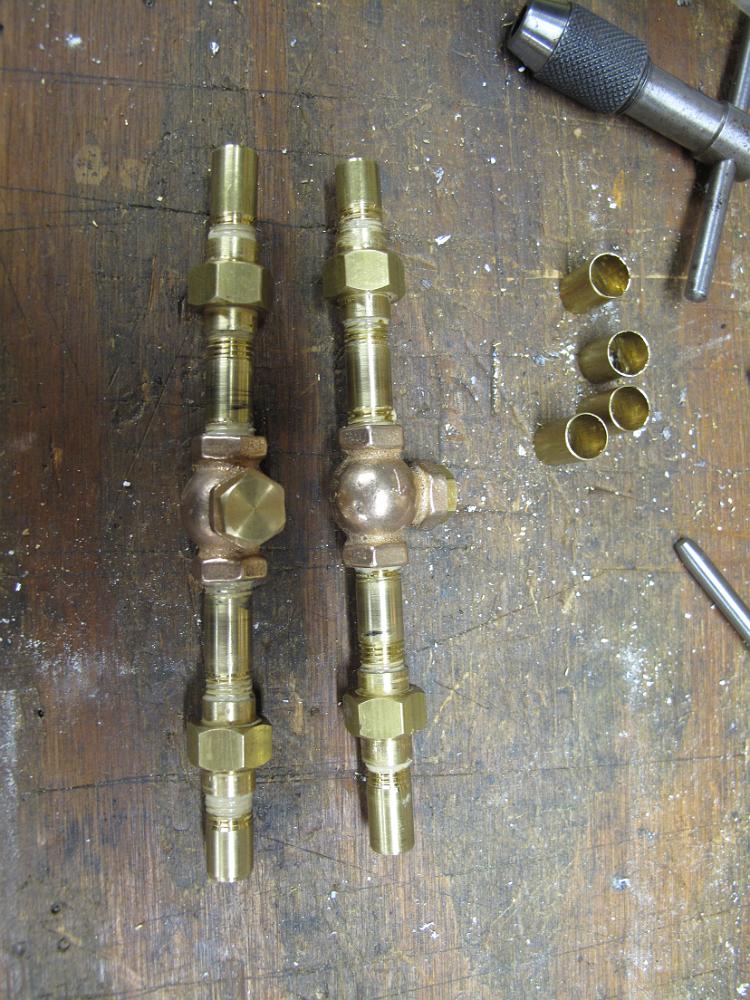
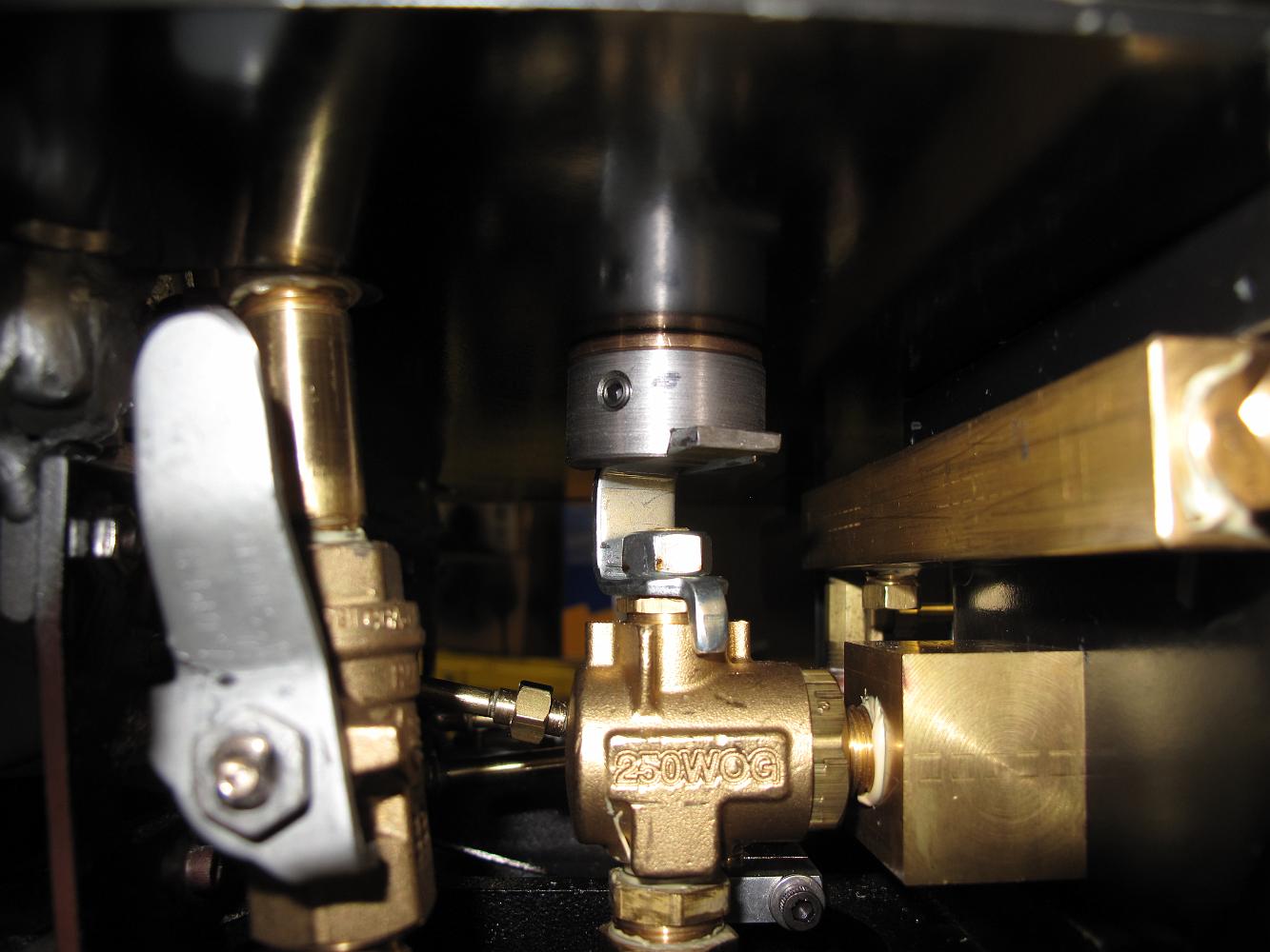
1-Nov-2011 The blower valve is installed. I can't believe this fitting took us one night to install, but it did. Shown is the custom 1/4 tube compression elbow…
20-Feb-2012 Skipping a work night due to bad weather (snow/ice), we start right in on the Auxiliary Air Manifold when we get back into the workshop. We decide…
20-Feb-2012 A nights work produces the Aux Air manifold. I did not have a 1/4" drill long enough to bore the manifold to a blind hole, so we drilled it our from…
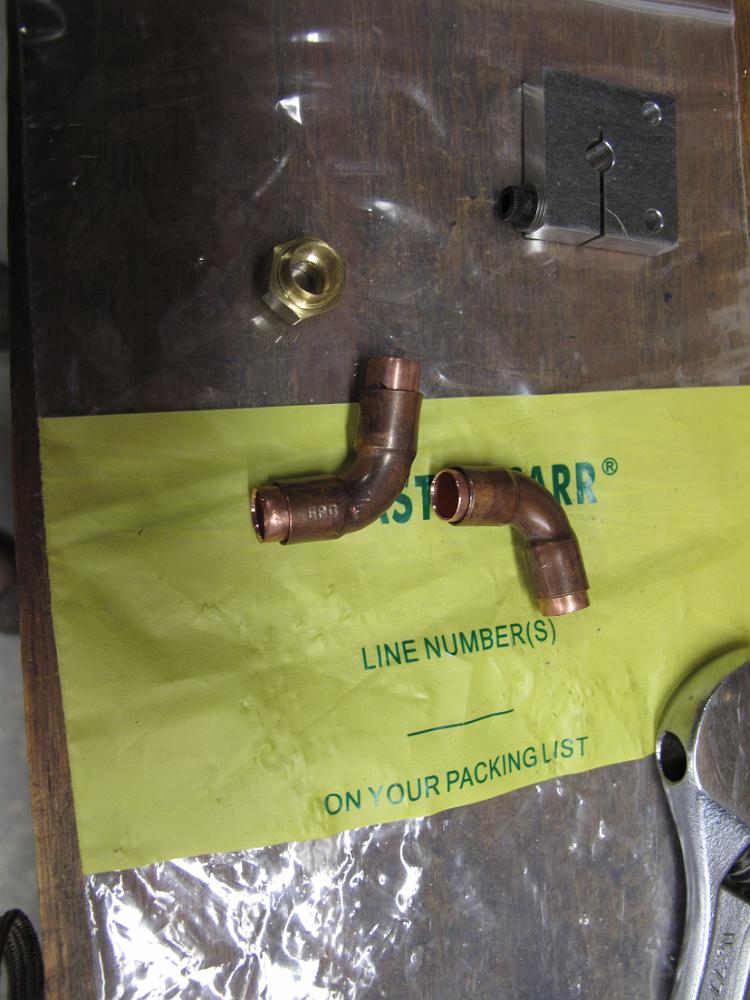
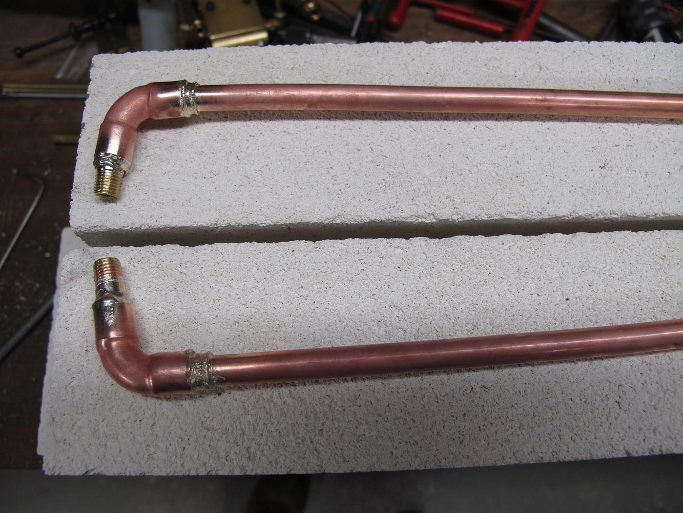
27-Feb-2012 We start to work on plumbing the Injectors. Pictured here are two 1/8 copper elbows, heated and opened up to something like 110 degrees. The…
27-Feb-2012 The Aux Air Manifold installed with the Atomizer Main Air Valve also installed. One good thing about this longer manifold is we have four screws…
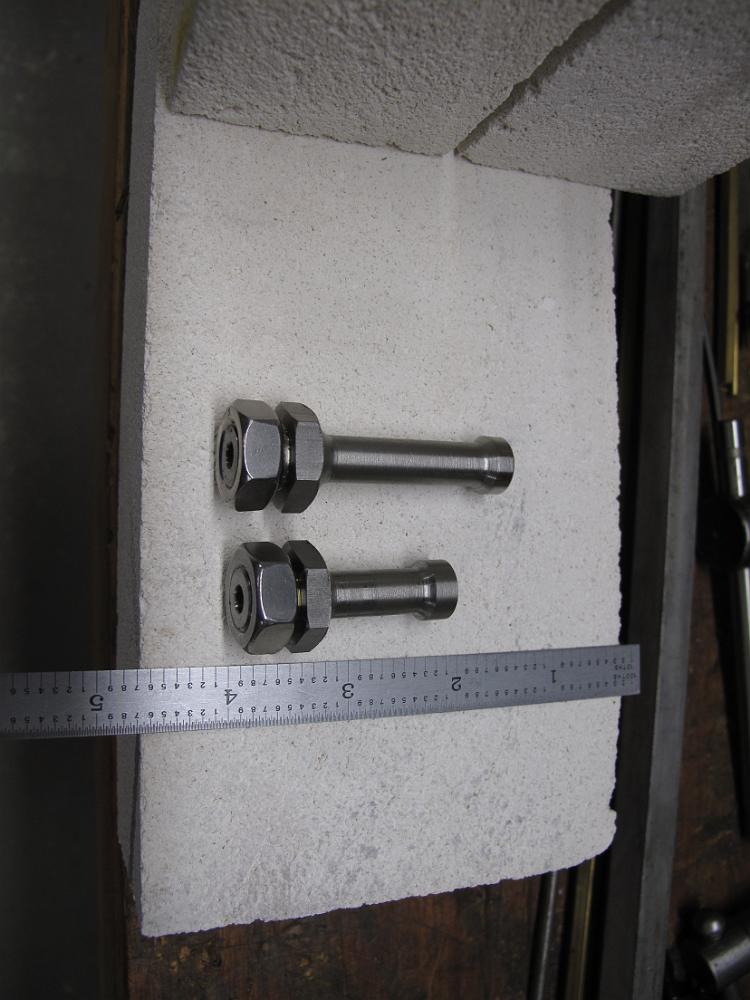
5-Mar-2012 Bill turns two valve stanchions our of 303 stainless while I work on some plumbing. They are for the Fuel and Atomizer valves.
11-March-2012 I puzzle out the bends required for the water lines, using thin wall 5/16" brass tubing.
22-Mar-2012 Plumbing the fuel line to the burner. This is basically to print. It did require we make six elbows.
26-Mar-2012 Another hole in the cab floor -- milling a pocket for the fireman's side combination washout plug and boiler fill.
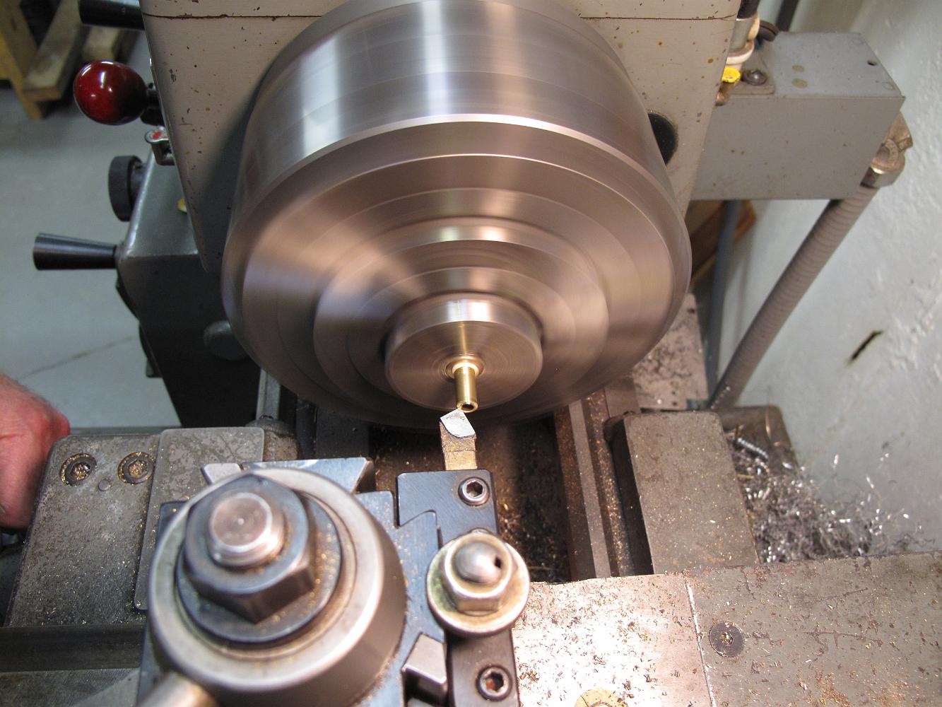
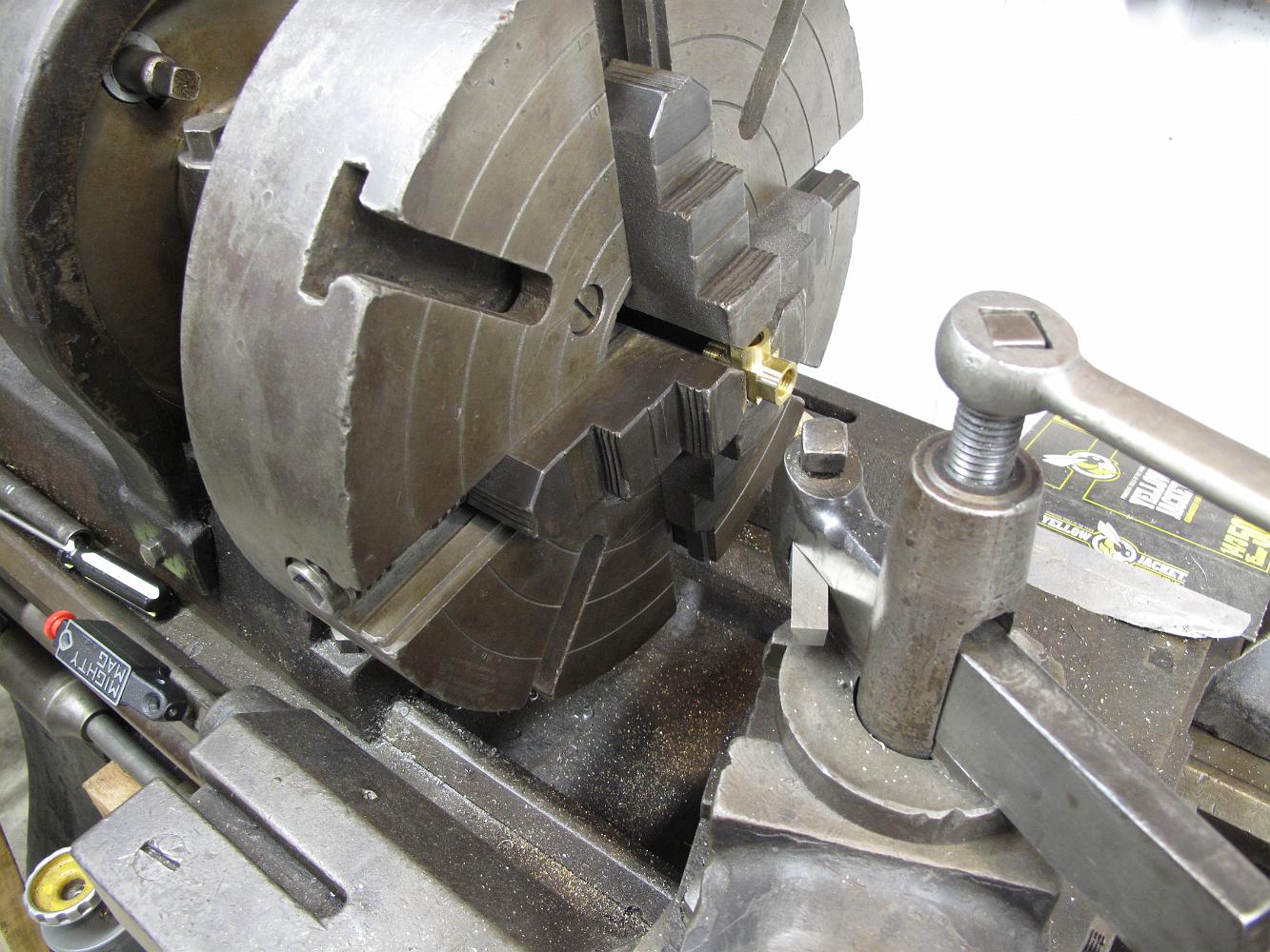
26-Mar-2012 A small part in a big 18" chuck! Bill had the good Clausing lathe tied up making fittings, so I oiled up the old Rahn-Larmon big lathe to turn the…
26-Mar-2012 A trial assembly of the boiler fill plumbing. The garden hose male connector will be shortened and modified to be a dust plug. With a little…
3-Apr-2012 New poppet water check valves to be installed after the injector output. Although there is a boiler check at the other end, these checks keep the…
3-Apr-2012 Bill has finished another batch of 3/16" fittings and plumbs up the atomizer line from the fine control valve to the burner. He also made up another…
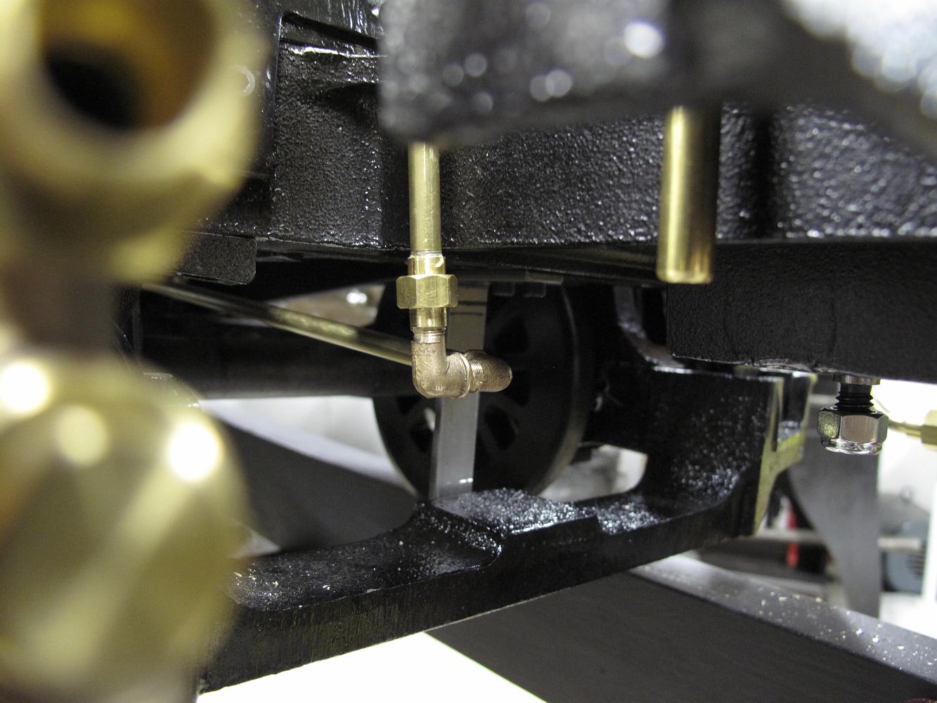
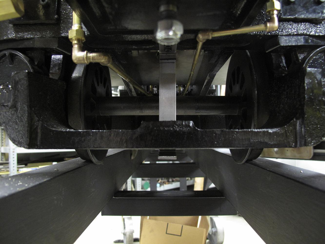
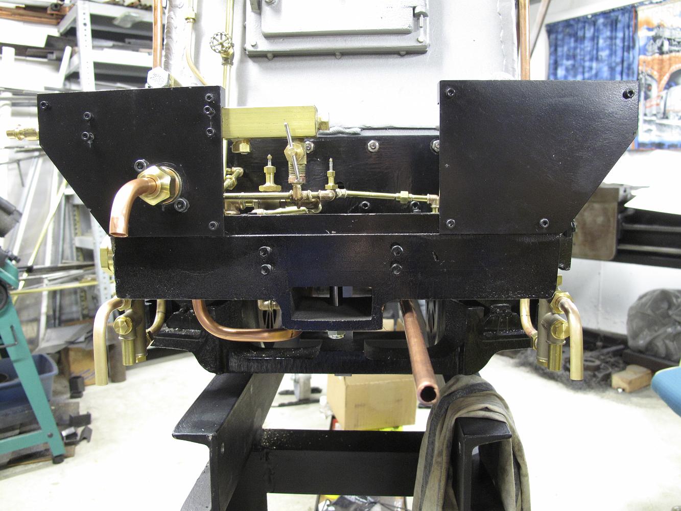
3-Apr-2012 And here's an under frame peek at the fuel oil and atomizer lines going from the cab to the burner under the firepan.
9-Apr-2012 We start into the axle pump bypass valve installation. I've purchased a 90 degree ball valve to fit into the crowded under-cab space. The inlet is on…
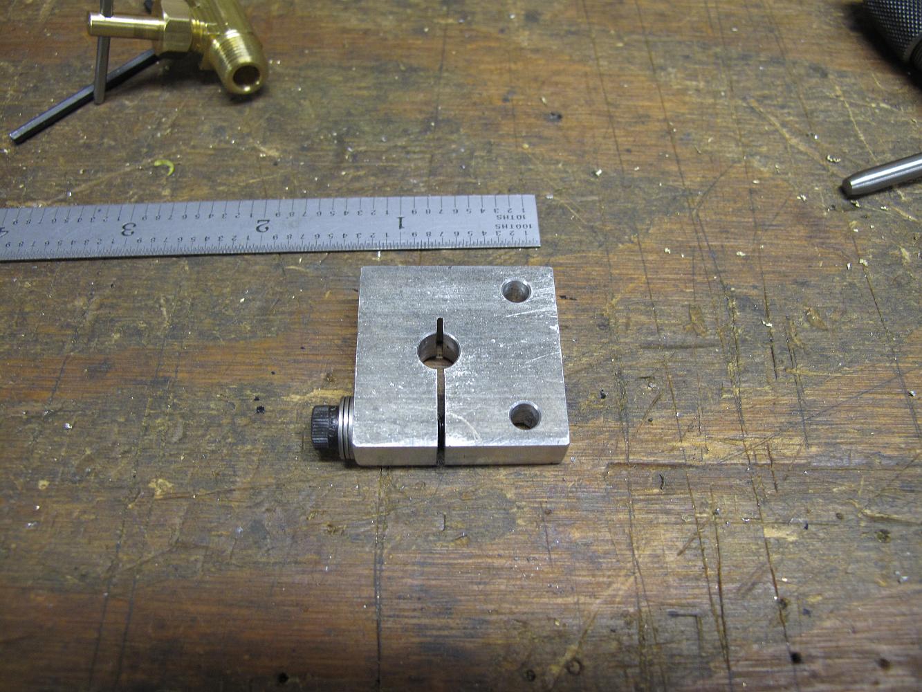
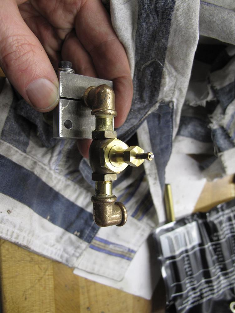
9-Apr-2012 We've turned down the hex flats on a flare nipple plug (male thread) and later that evening silver solder it into the brass block (above it).
20-Apr-2012 The water bypass valve mounting block has been mounted on the left cab support bracket, and a test piece of pipe flared and put on the protruding…
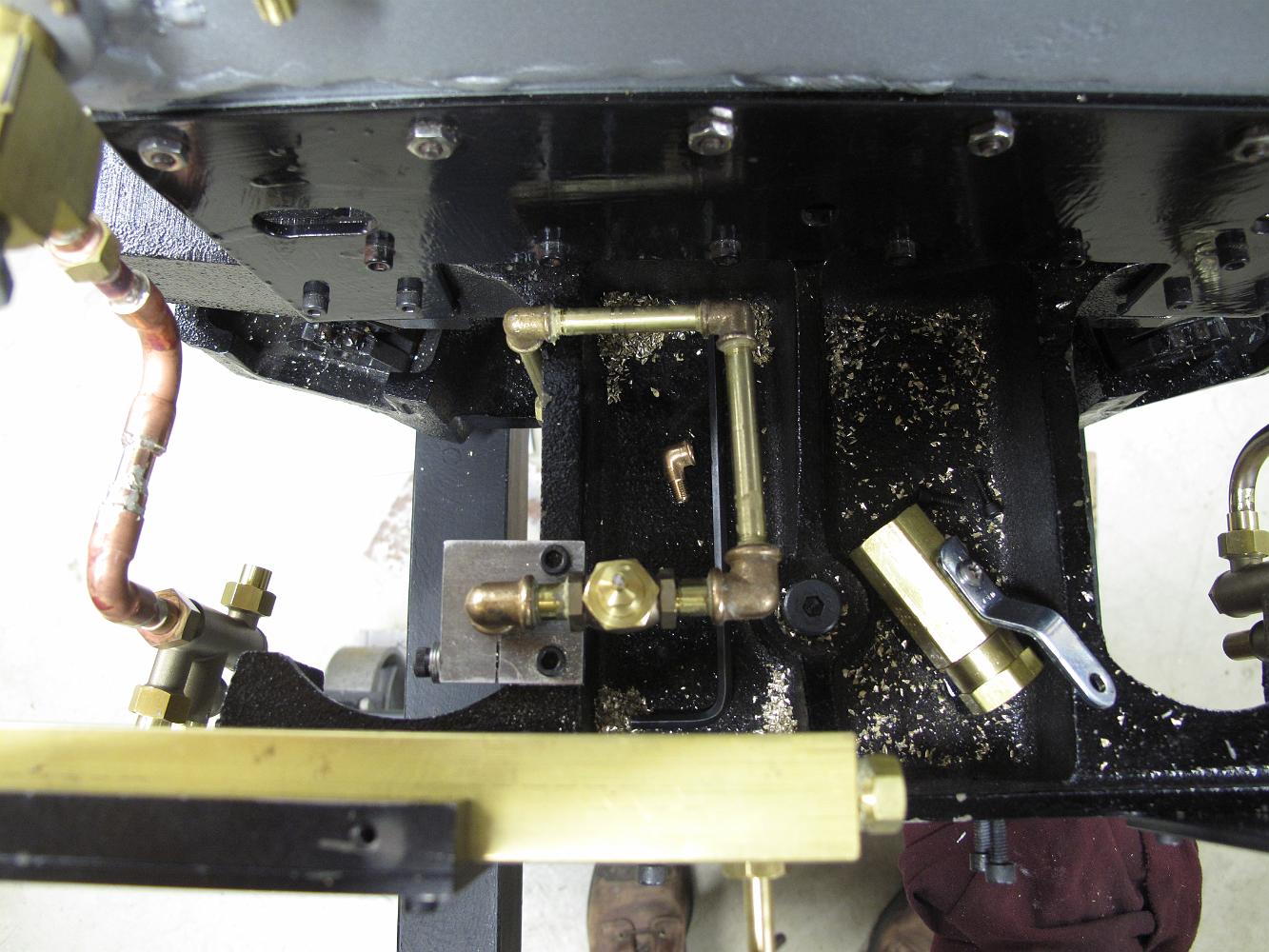
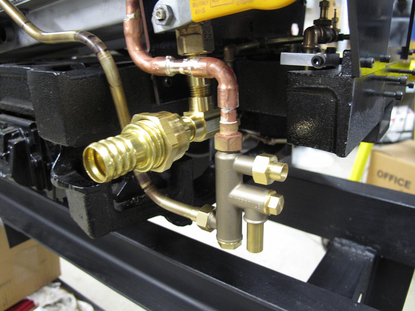
20-Apr-2012 Things are coming together, plumbing-wise. Installed is the M-F-F tee to the boiler fill piping; the axle pump water bypass valve installed in the…
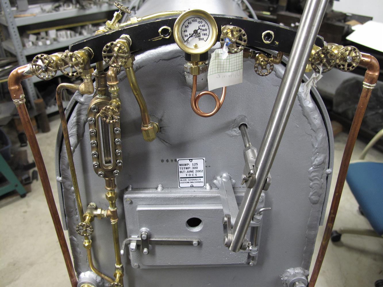
20-Apr-2012 The backhead is looking busier with all this plumbing installed! I wonder if anything leaks?
20-Apr-2012 I end the day working on the water connections from the tender to the engine, silver soldering the pipe to the injector union fittings.
20-Apr-2012 There's no good way, at least as far as I could see, of getting through/around the trailing truck frame connection point. No room above since the…
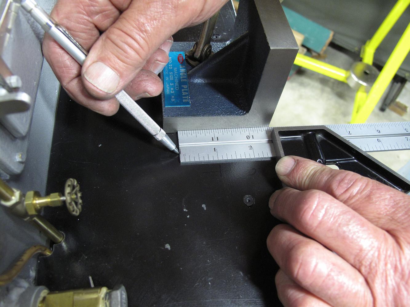
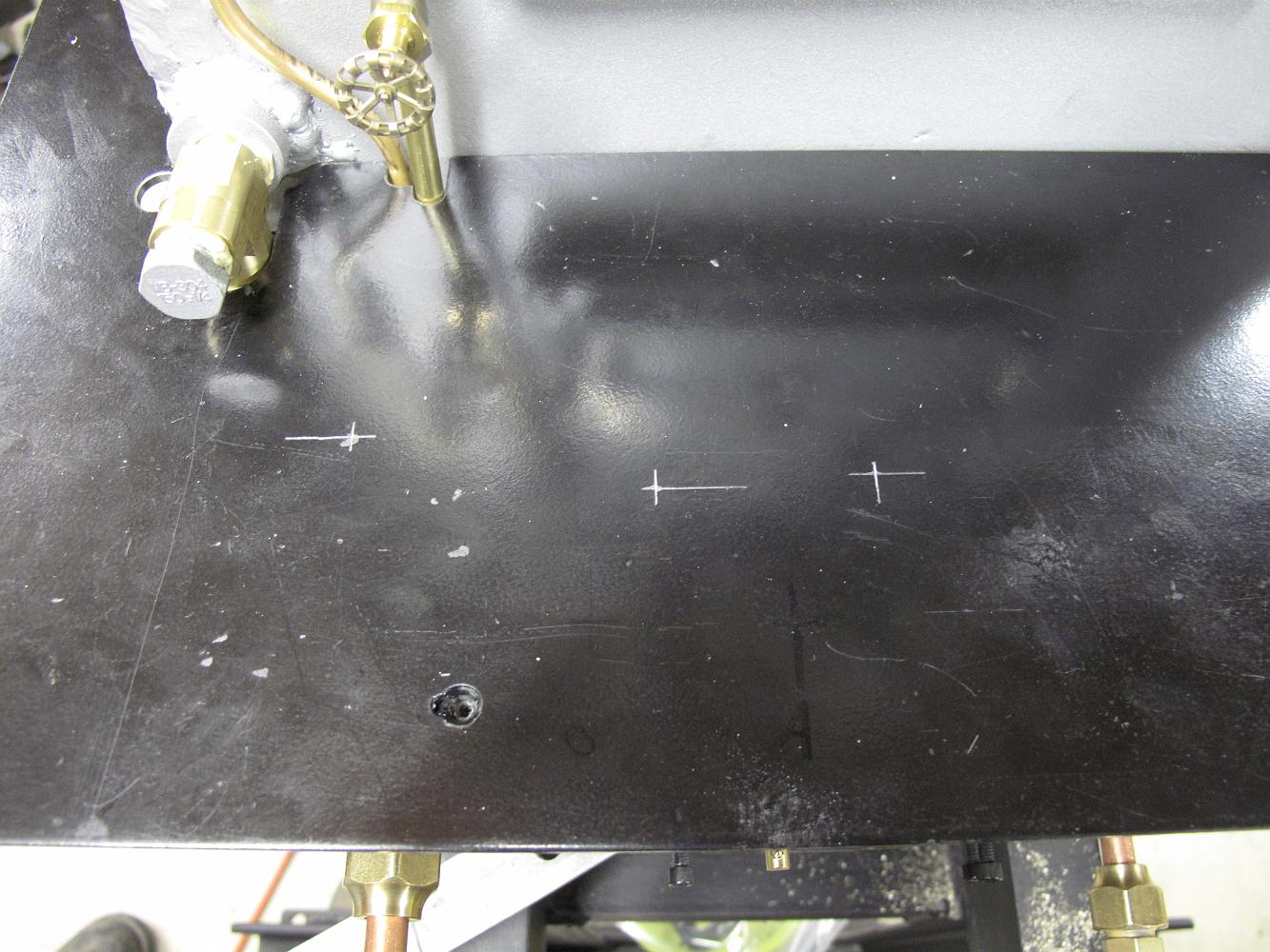
23-Apr-2012 Doing our best to accurately lay out the valve extension holes in the cab floor. Using a known reference point, the edge of the cab floor, we do our…
23-Apr-2012 Doing our best to accurately lay out the valve extension holes in the cab floor. We've clamped a small angle plate to the floor to keep the…
23-Apr-2012 Doing our best to accurately lay out the valve extension holes in the cab floor. Scribing the Y coordinate on the floor. We repeat this for all…
23-Apr-2012 The cab floor with location marks, ready for drilling. We next take the floor to the mill and using a stop rod in the vise so we can more accurately…
24-Apr-2012 I continue to work on connecting up the temporary tender. A drawbar is made up from the scrap box, and plumbing lines are completed.
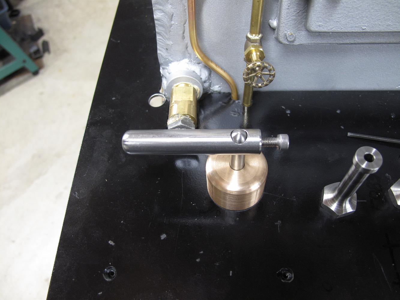
7-May-2012 Freshly turned stainless steel handle extensions. The print calls for us to move the original handwheels from the valves to the top of the…
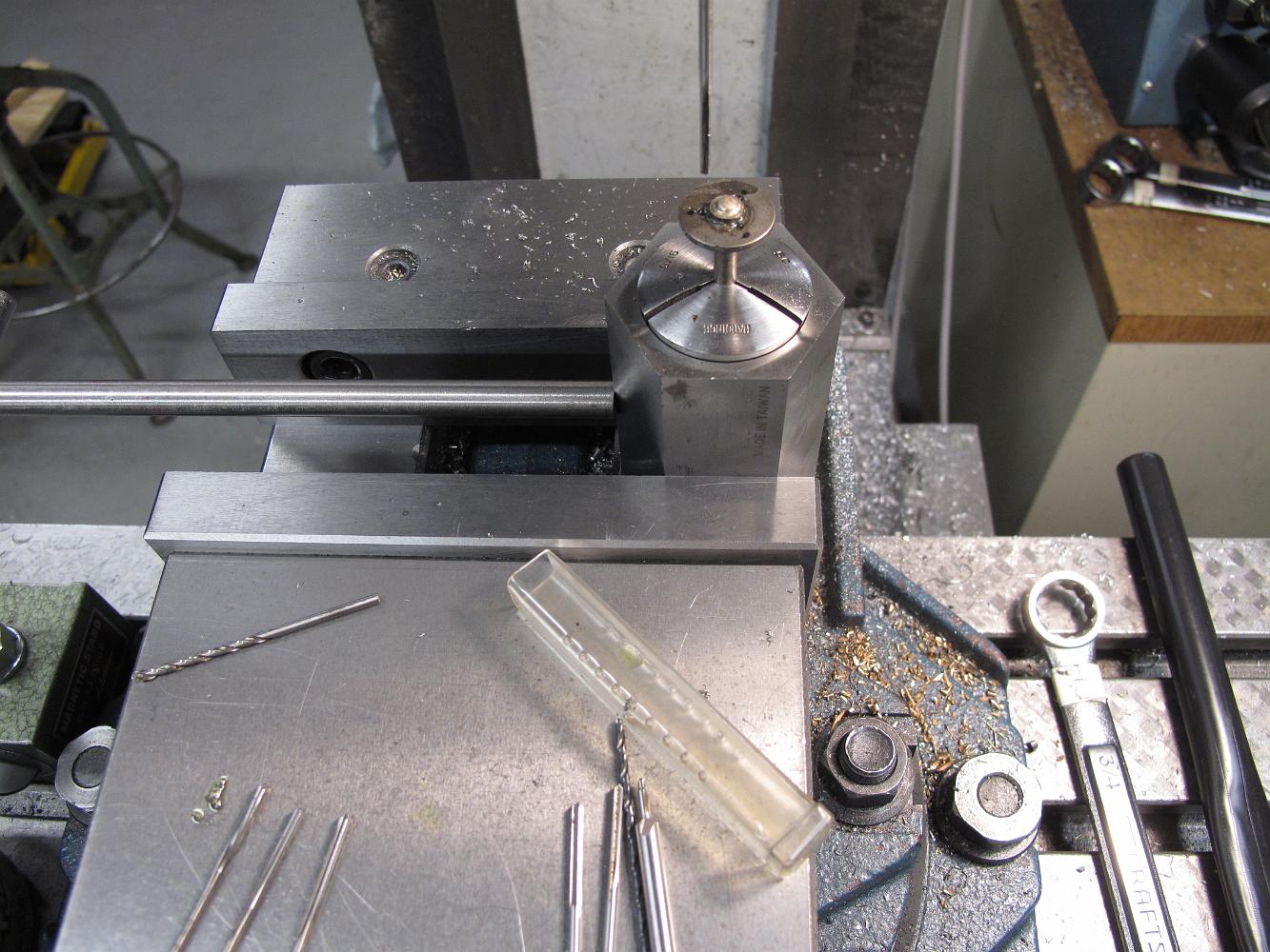
14-May-2012 One valve extension we CAN put a 1/4" square hole into - the water bypass handle extension. We've drilled a 1/4" hole in the stock and using a…
14-May-2012 Using a square collet holder, I've machined four flats on the 1/4" SS rod for a nice fit into the square holed stock.
14-May-2012 The valve extension installed for a trial fit onto the factory lever handle (which has been bent over into a u-shape).
14-May-2012 Drilling the underside of the cab floor to anchor the water valve handle extension bushing. You can also see the SS nuts holding the fuel and…
14-May-2012 Using a stop rod to relocate the part each time, and a collet holder, we machine a four sided flat into the extension rods. The machining sequence…
14-May-2012 We decide to use two already square broached handles from SuperScale, leaving the original valve handles on the valve stems.
18-May-2012 A little more lathe work and with the help of a 5-40 die, I've put threads on the end of the extension rod to tightly hold the handle to the stem.
18-May-2012 A little bit of heat and some silver solder joins the stem to the disk with one of the nicer looking soldering jobs I've done in a while.
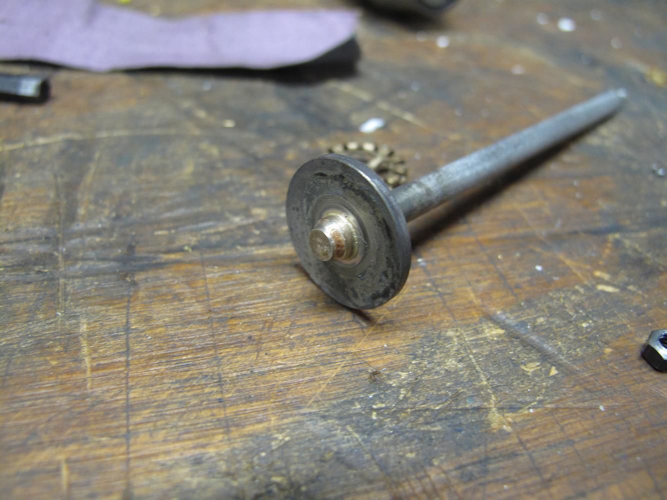
18-May-2012 We've decided the valve stem extension should have pins that stick down and engage the webbing of the original valve handles. The oil valve has an…
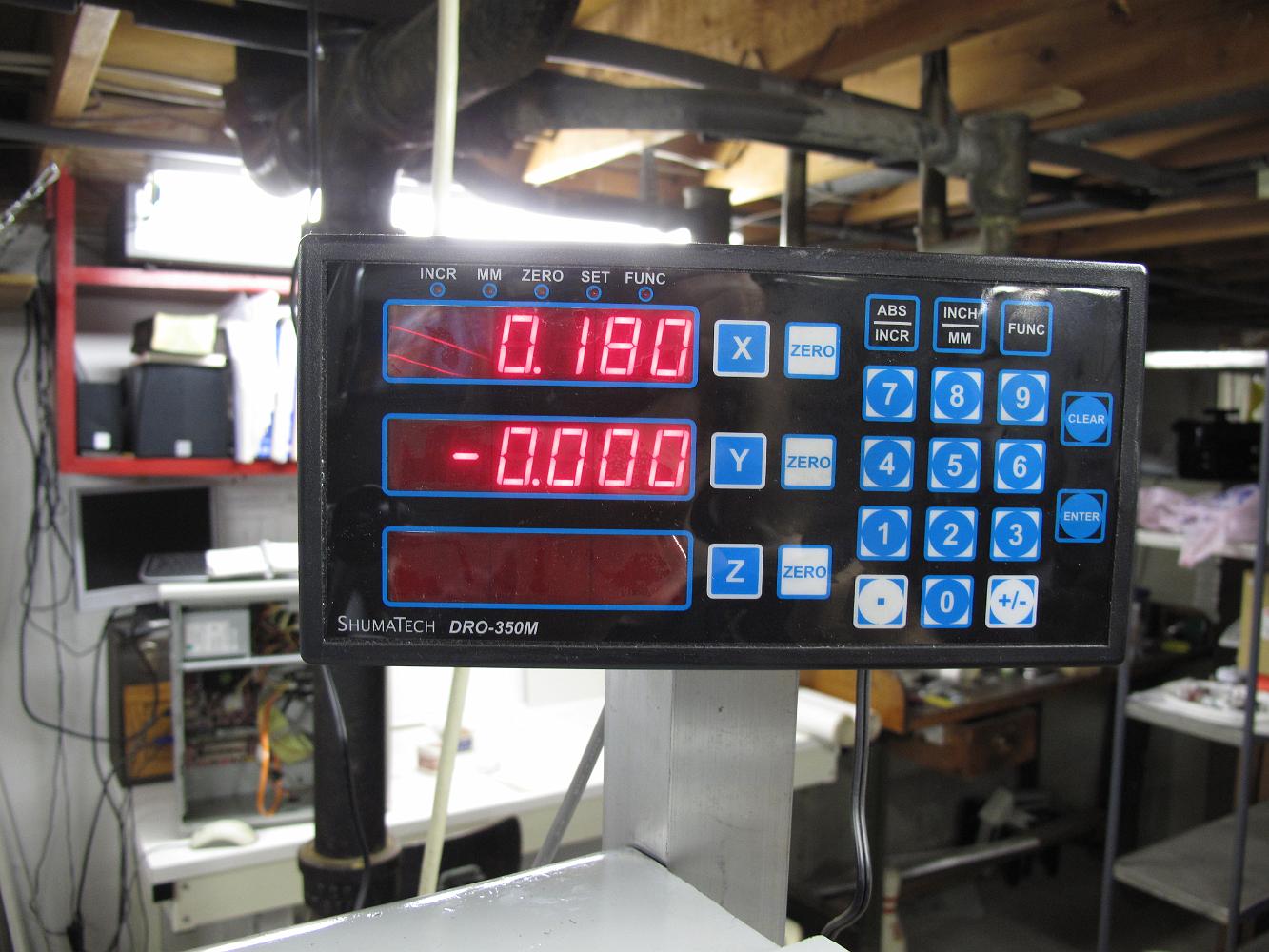
18-May-2012 I've centered the extension in the mill and determined that the pin spacing should be 0.180 over from center.
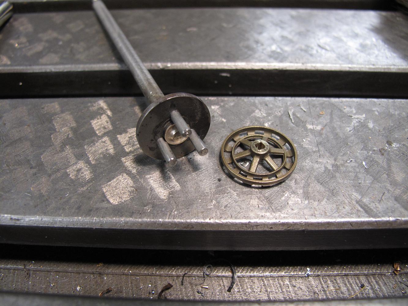
18-May-2012 All three 3/32" diameter pins (5/8" long) have been pressed into the disk and engage the handwheel spokes with little slop.
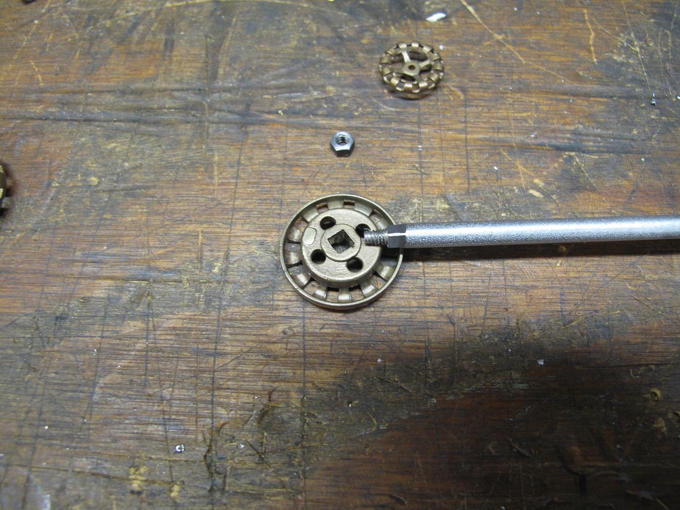
19-May-2012 I didn't want the atomizer handwheel to be the same size as the fuel handwheel, even though they are both identical. So I install the handwheel onto…
19-May-2012 The modified atomizer handwheel. A bit of handwork with a small file to take the sharp edges off gives a distinctive handle gloved hands can easily…
19-May-2012 View below the cab floor of the installed valve extensions, showing the engagement of the pins into the original valve handles.
20-May-2012 I need to put a flat on the upper part of the shaft to give the setscrew in the handle room to bite without raising a burr on the shaft. Previously…
21-May-2012 By the time I got the camera out, Bill had finished turning six stainless steel plugs for the overfire tubes. We will find out if some, all or none…
4-Jun-2012 With the freight elevator out out of service, we can't get the engine out of the basement for first fire up. We turn our attention back to the cab…
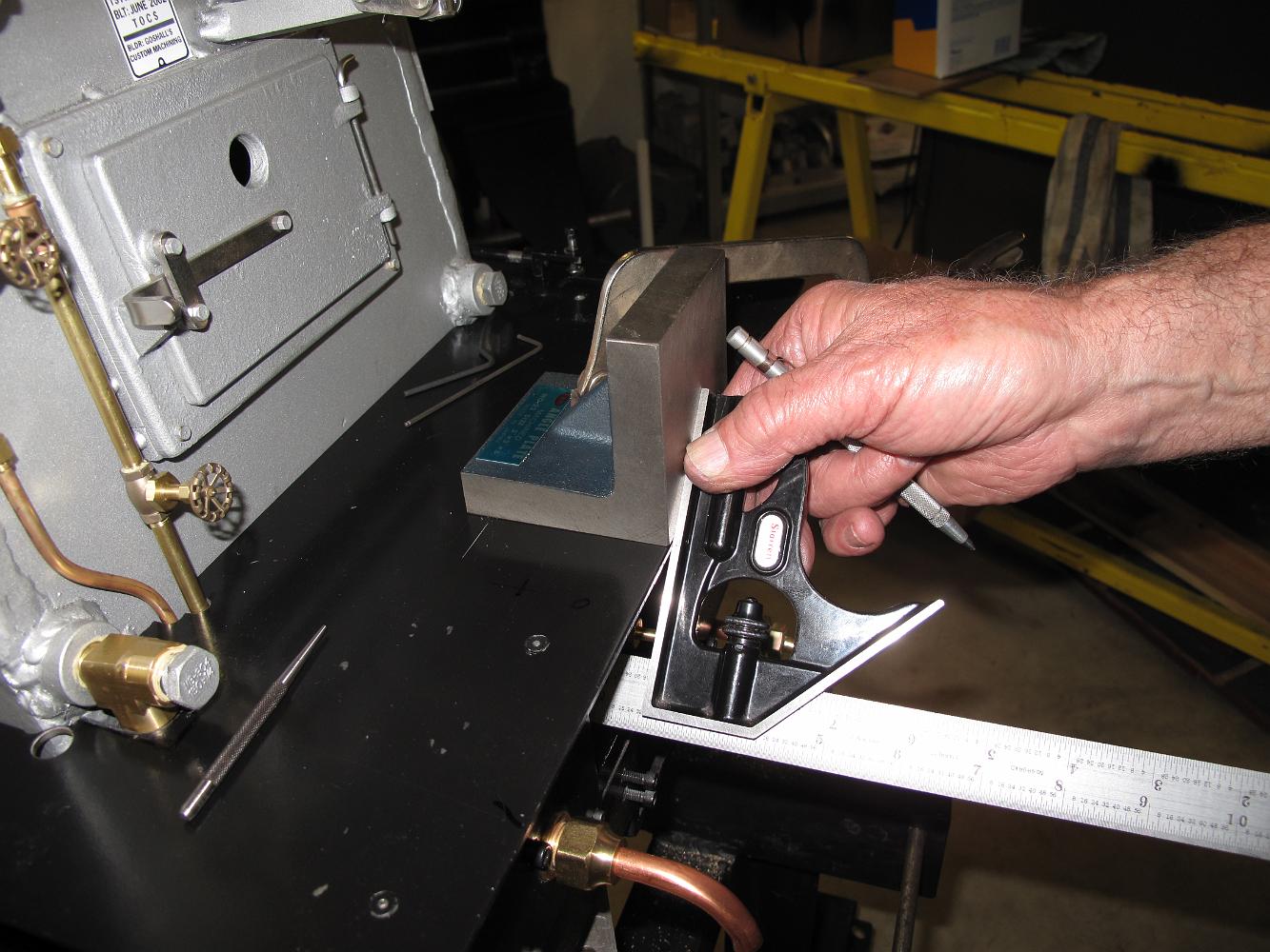
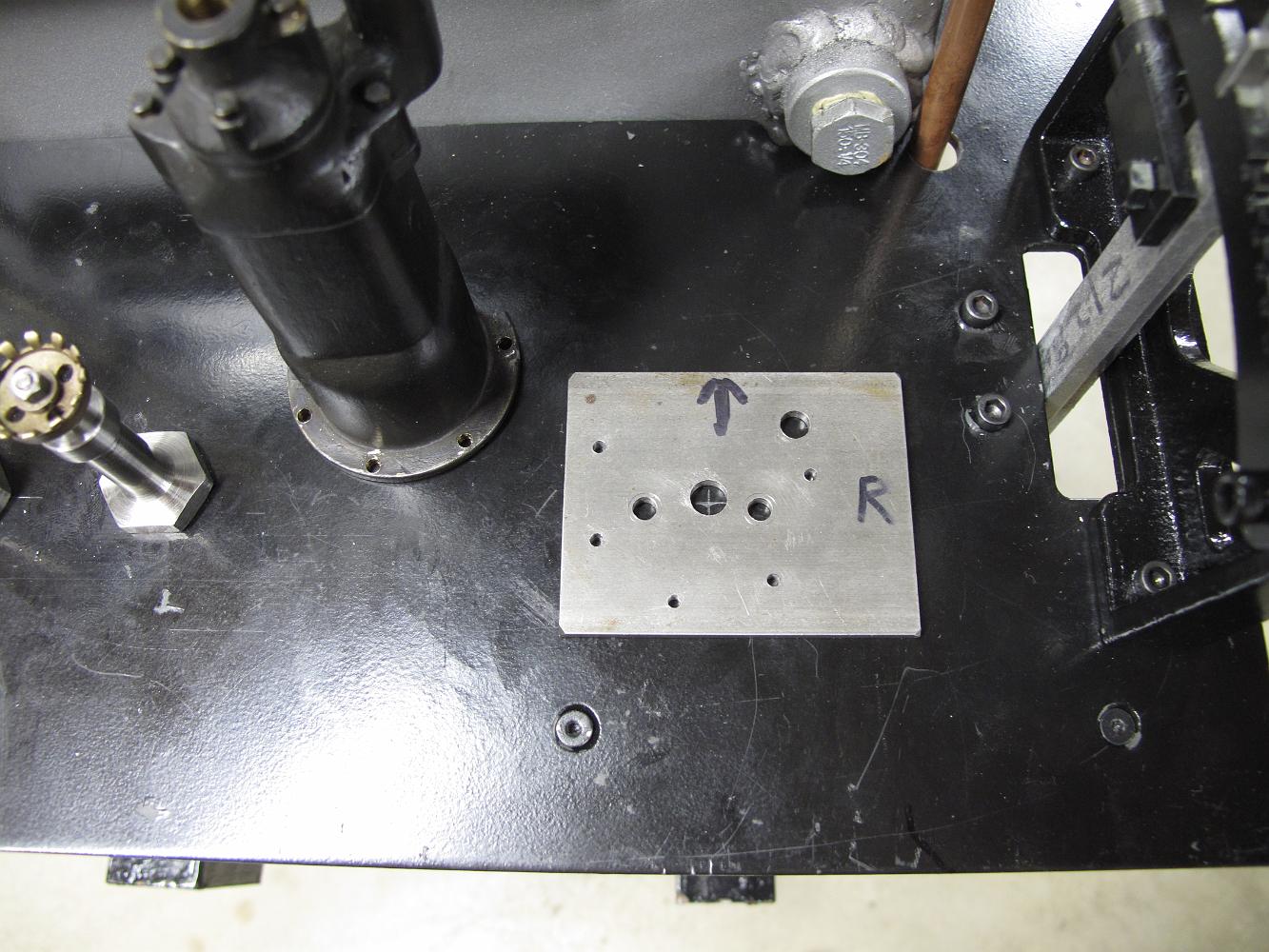
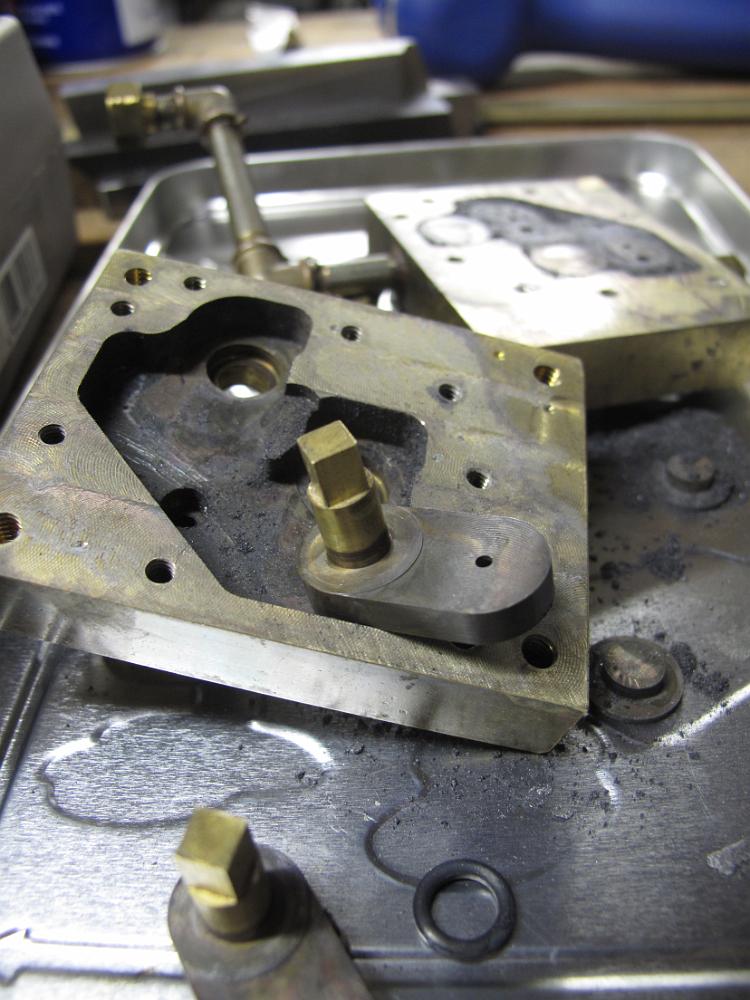
4-Jun-2012 Using the center hole from the template as a reference, we take measurements to locate the brake stand from known edges for accurate machining.
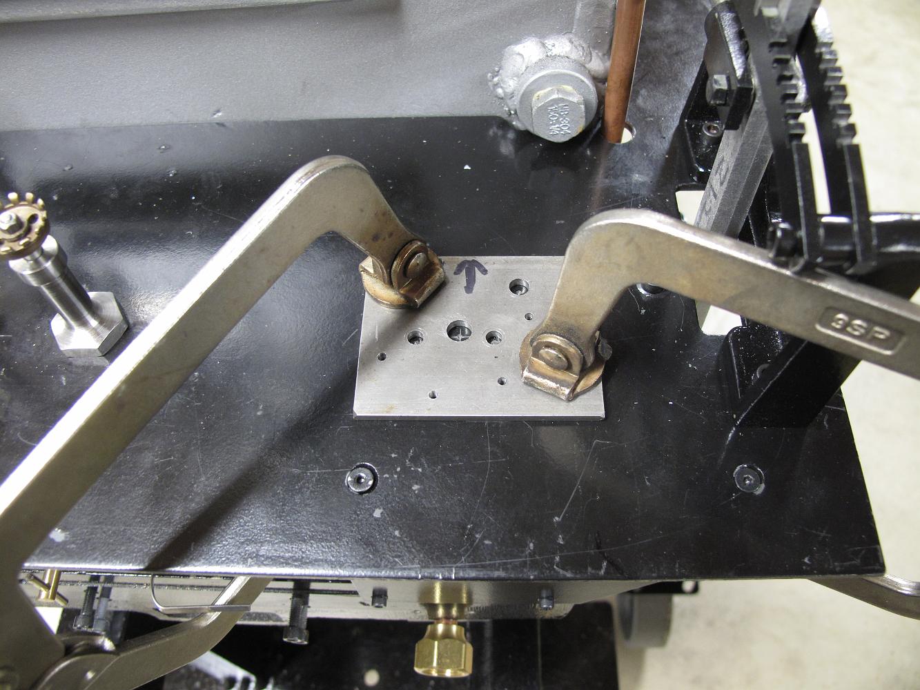
4-Jun-2012 We find that the firedoor, which hinges on the right, will almost hit the brake stand, so we move the centerline to the right a bit more. Although…
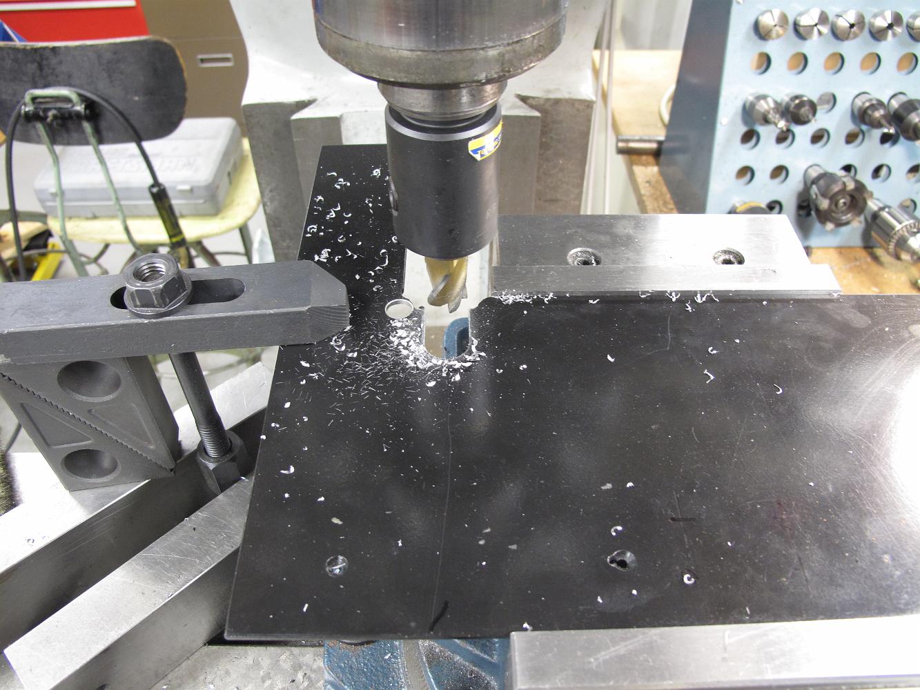
4-Jun-2012 I find myself not enthused about disconnecting all the plumbing to remove the cab floor to drill the brake stand holes and convince Bill to match…
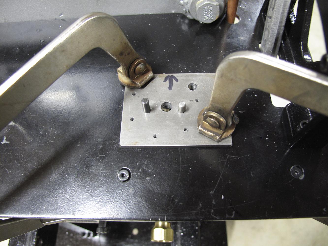
4-Jun-2012 With two holes drilled in the floor using the match plate, we put dowel pins in the openings to keep the plate from shifting anymore for the rest of…
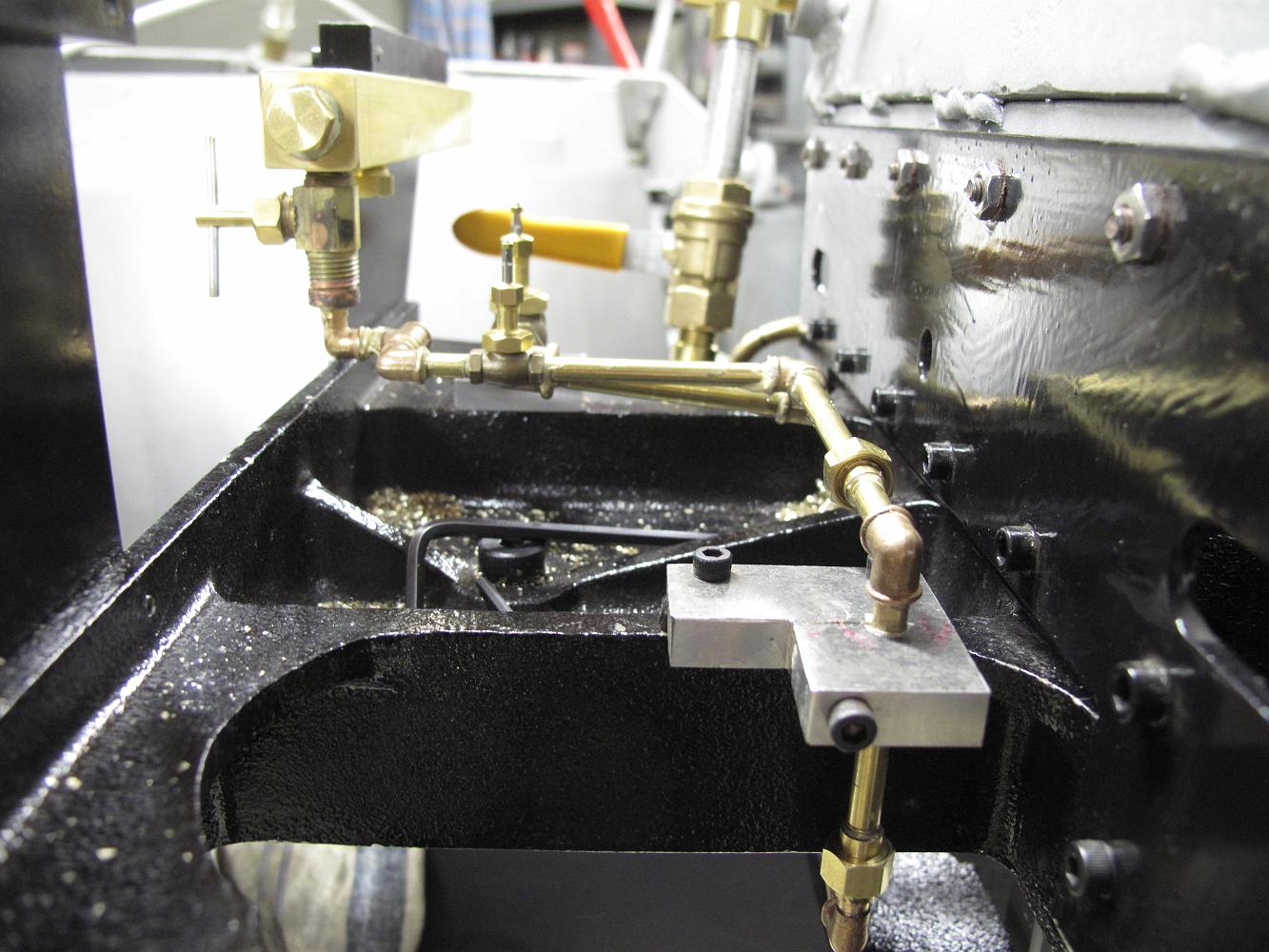
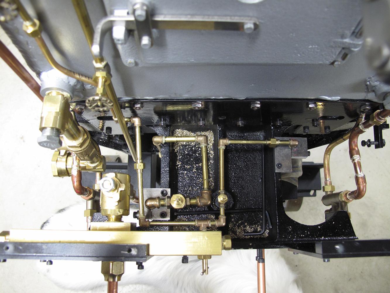
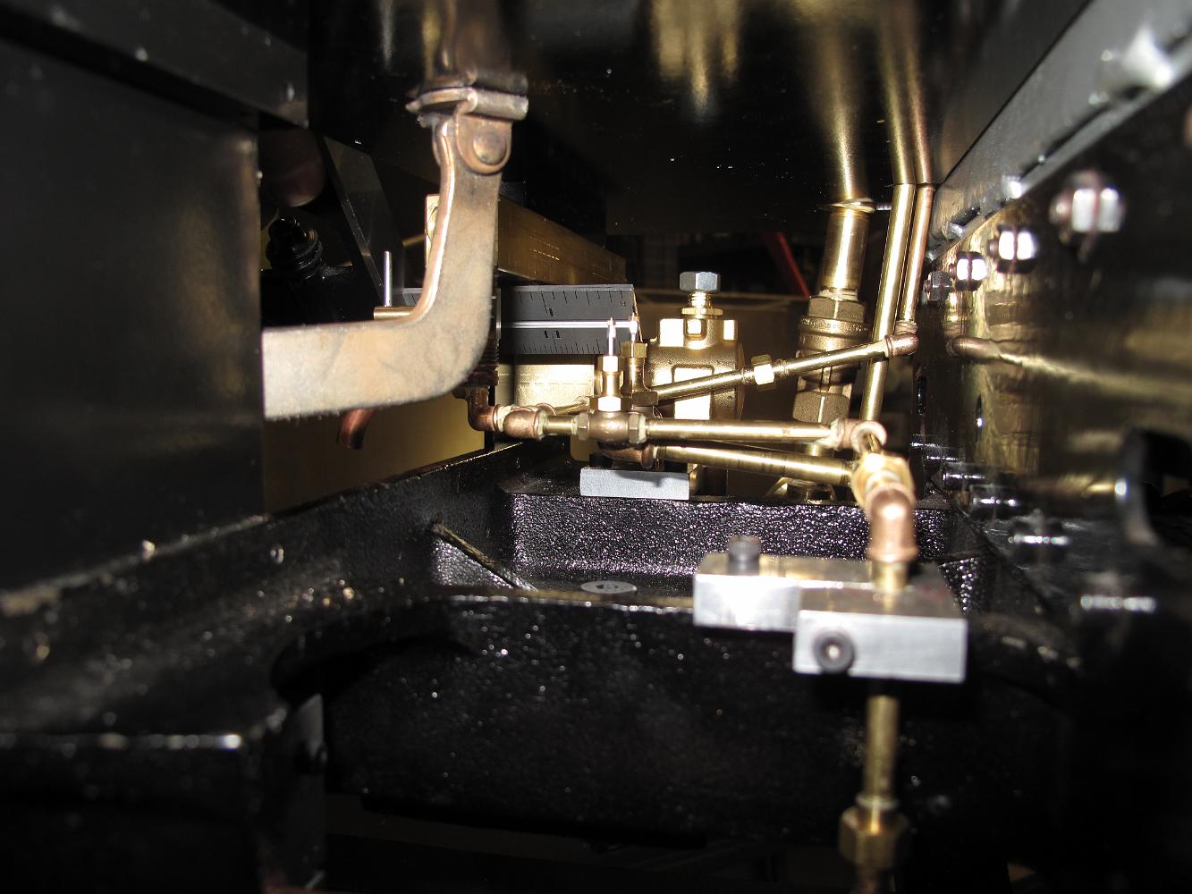
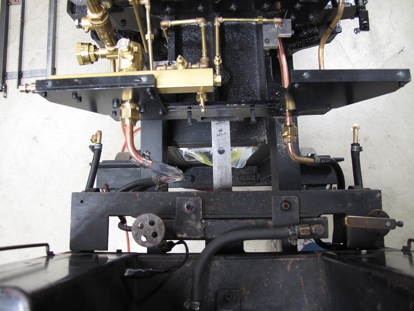
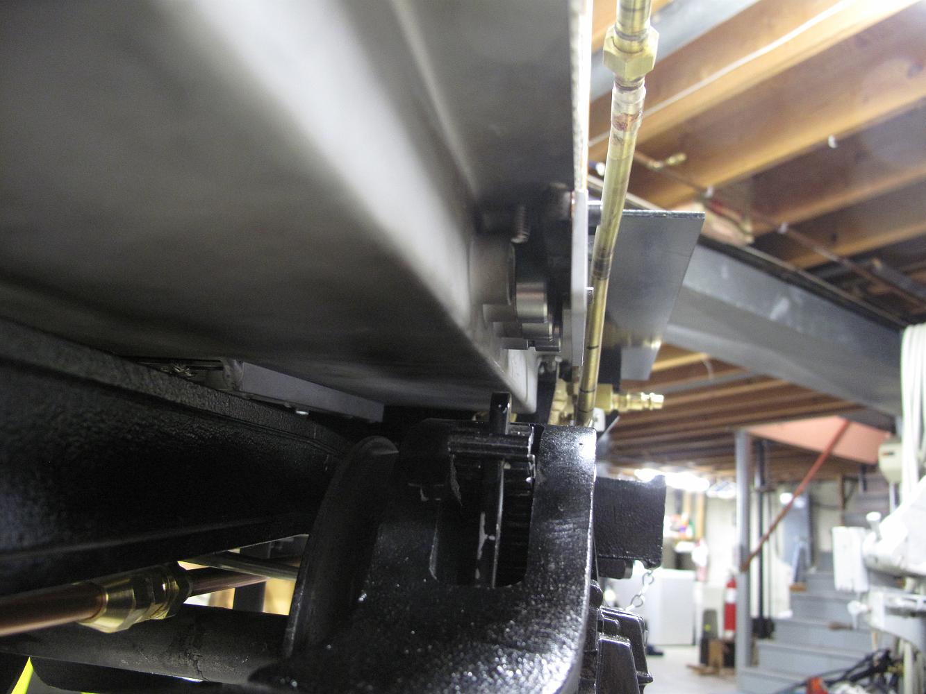
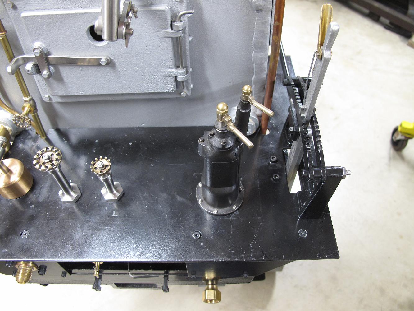
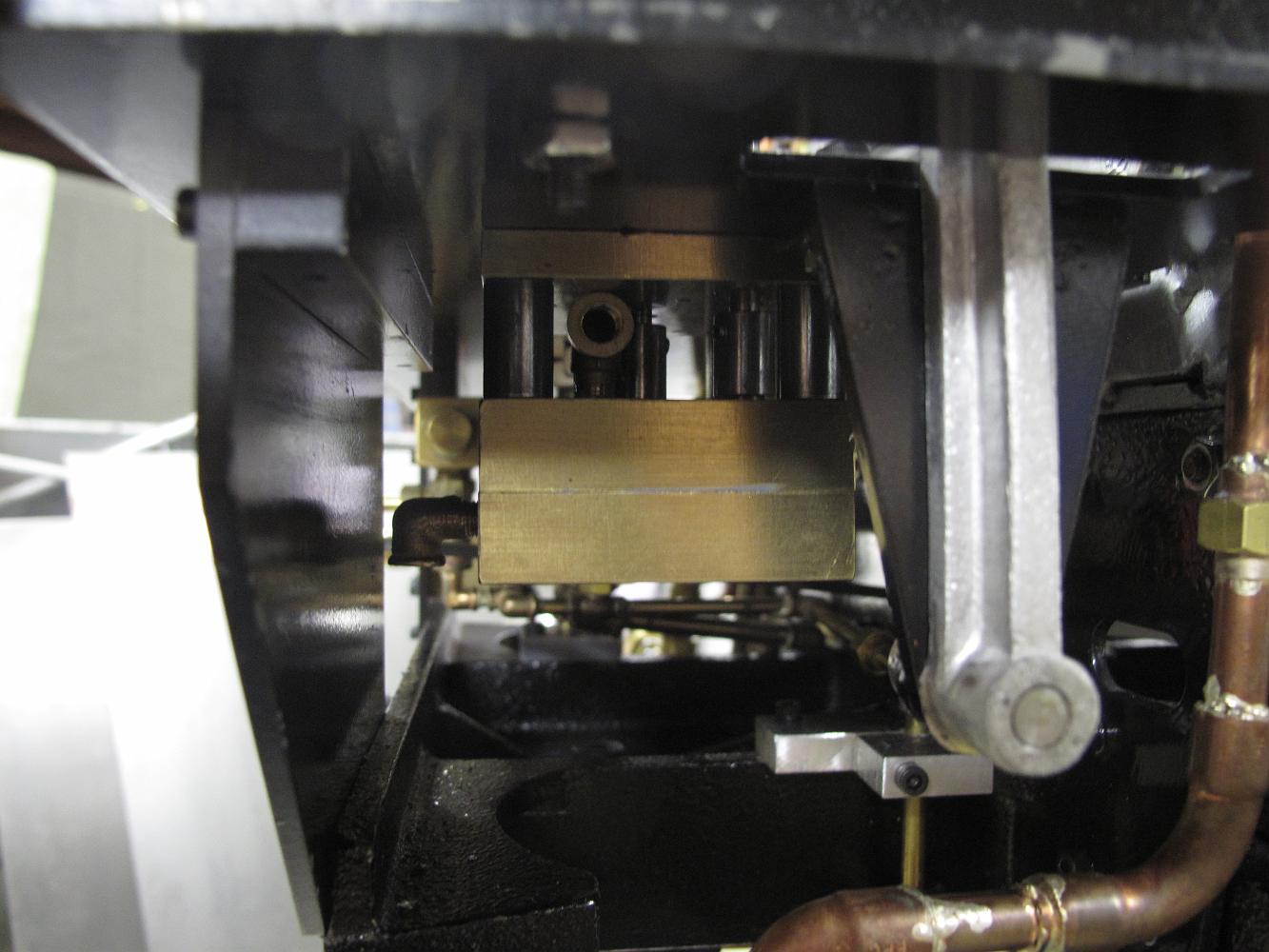
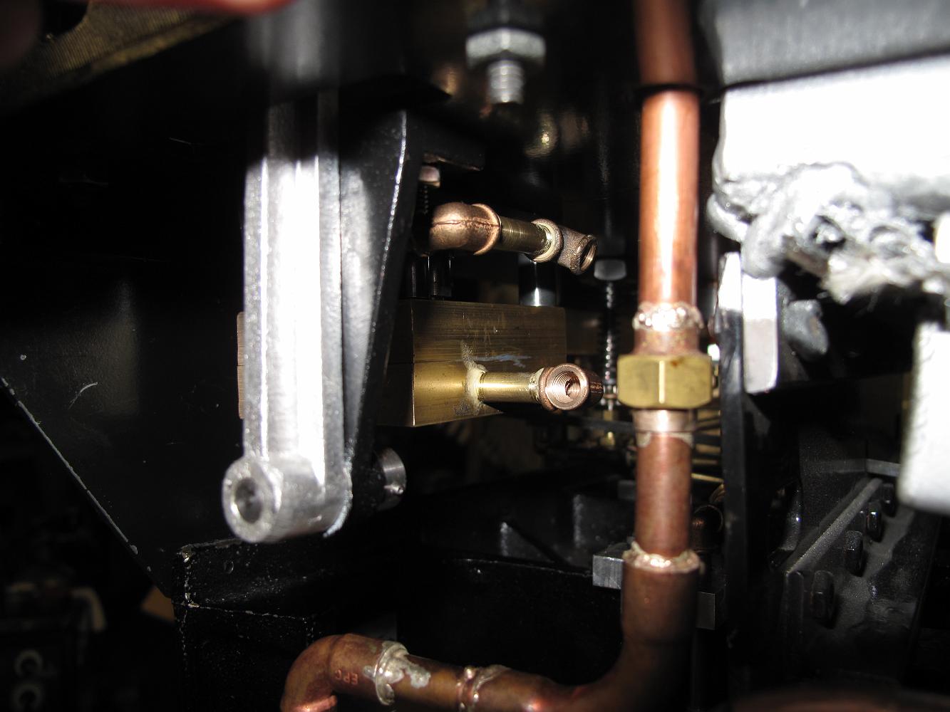
4-Jun-2012 The brake stand plumbing block below the cab floor. The plumbing block is very neat and self-contained, containing all the passages, valving and…
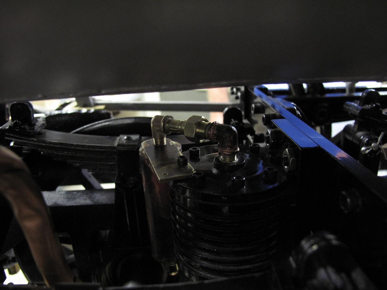
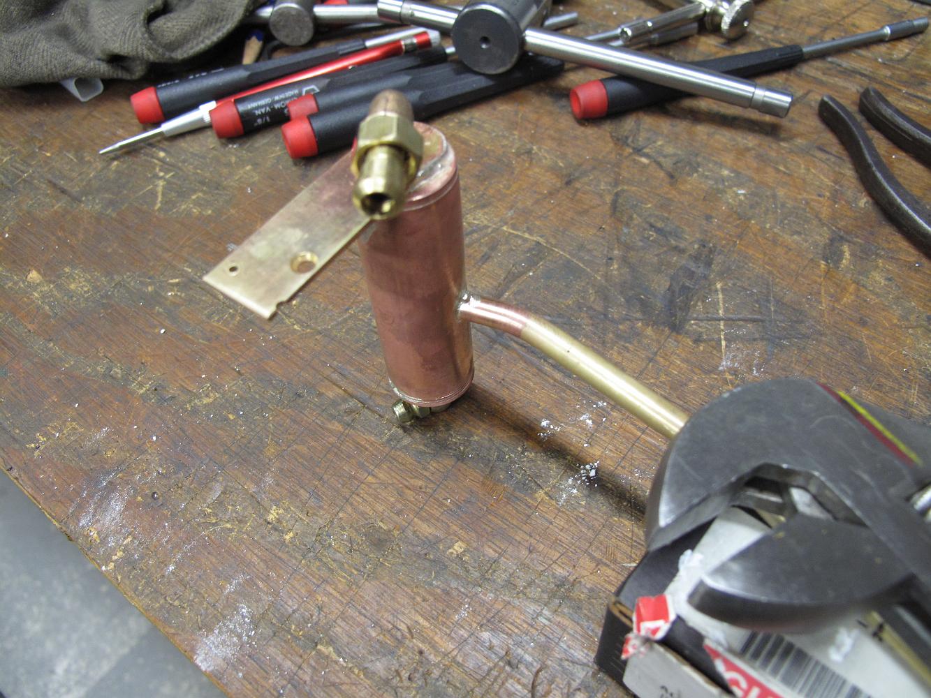
13-Aug-2012 The home-made steam/water separator all soldered up. The top pipe is steam to the brake cylinder, middle pipe into the side of the separator is…
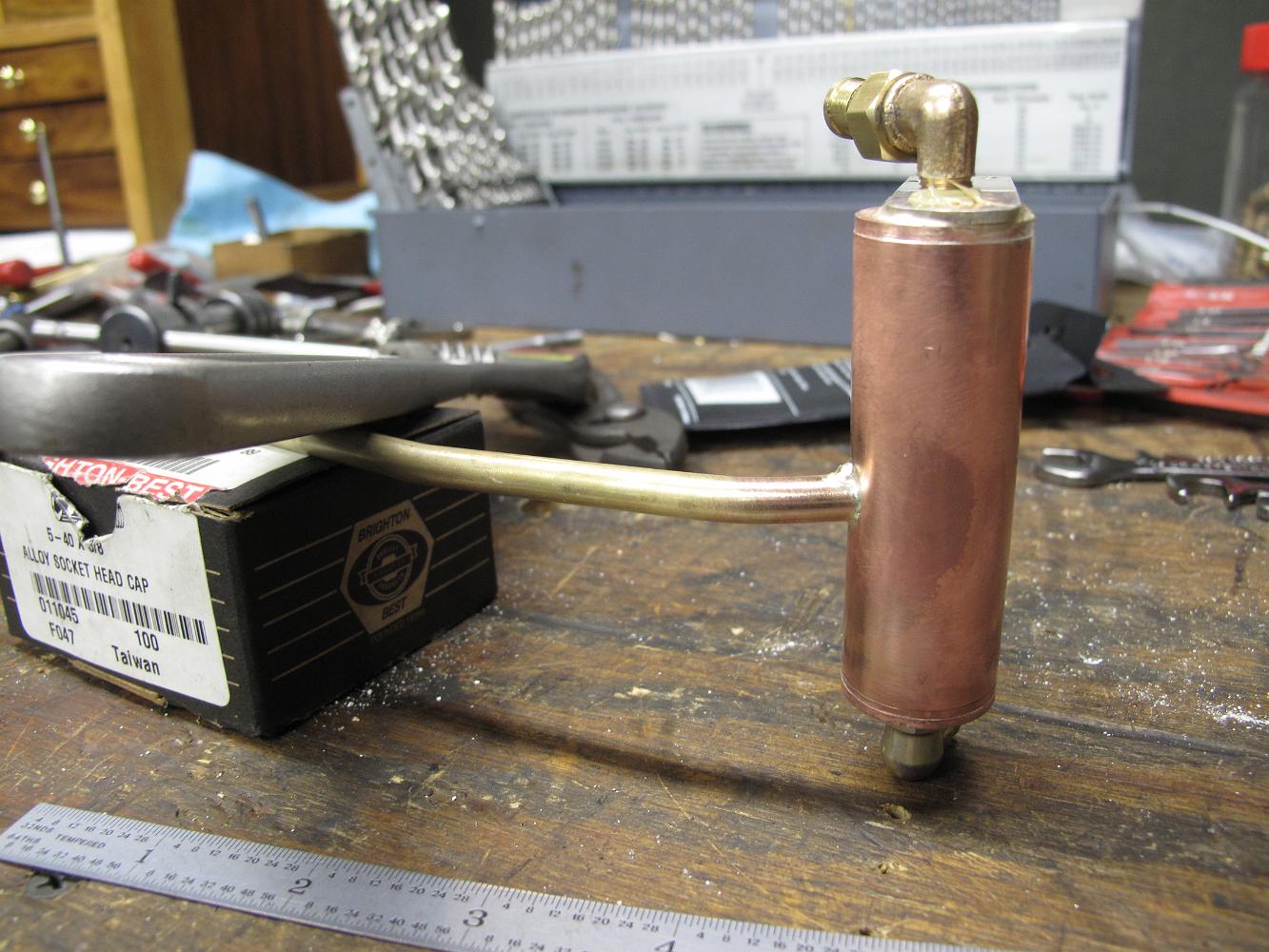
13-Aug-2012 Bill spent the evening making up more 1/4" fittings and short nipples to plumb up the brake stand valves.
9-Jun-2014 The brake valve locked up again, so I add a hydrostatic lubricator to the steam supply line.
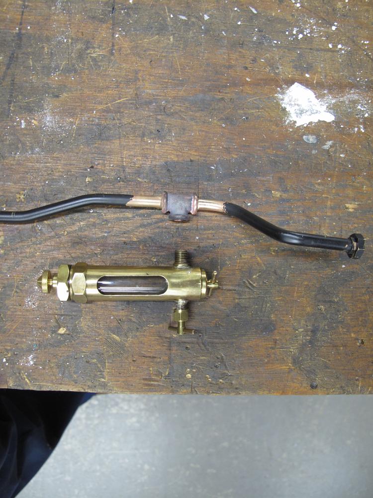
14-June-2014 We found the vacuum ejector someone else had built (top right) would only pull 12" of vacuum, which is not enough to set the brakes on the train…
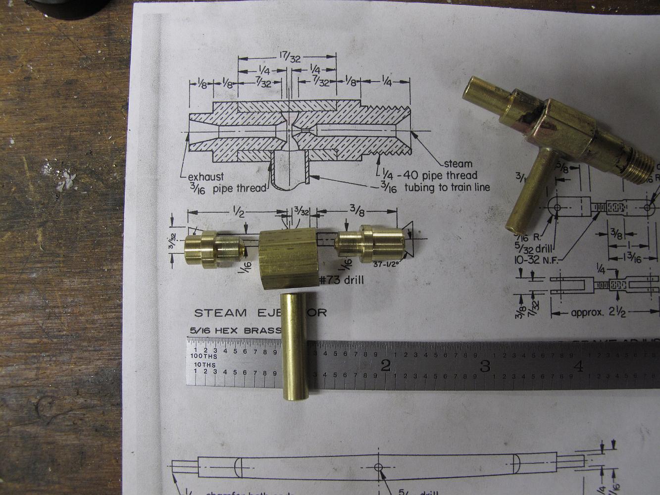
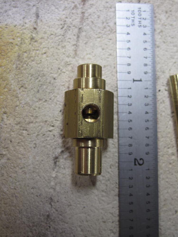
16-June-2014 This ejector sure is a small package. And we're not sure we have all the dimensions correct. After silver soldering the pieces together, we test it…
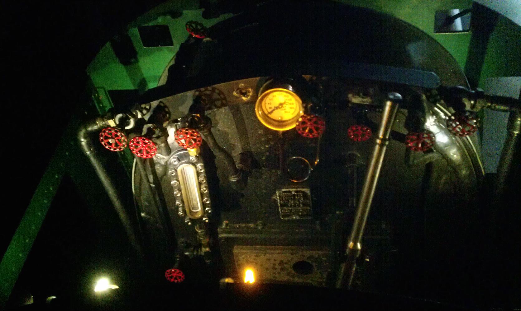
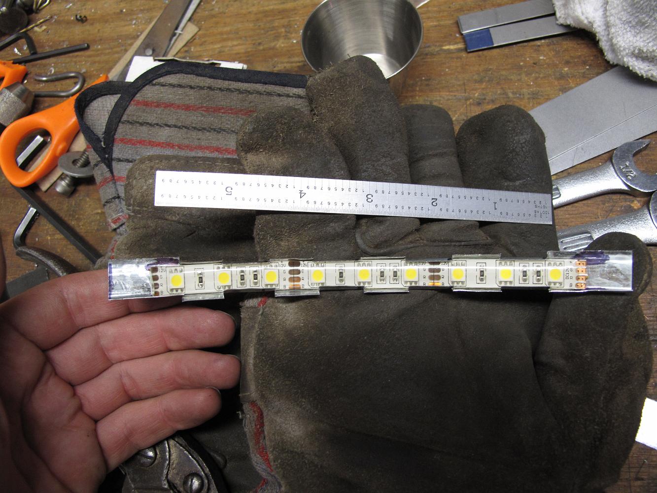
8-Sept-2014 Cab lighting, try #3 (#1 was a flashlight, no good. #2 was individual LED lights which looked good was were easily damaged) This is a flexible strip…
New Water Glass
18-Sept-2018 We fabricate a new waterglass using 'redline' borasilica glass and brass. We were having too much trouble in sunlight seeing the water level in the…